


COM
OUT
IN
K
A
REF
COM
OUT
IN
Vcc
Gnd
Ctrl
START-UP
CURRENT SOURCE
VALLEY
START-UP
CURRENT SOURCE
CURRENT
SENSING
OUTPUT
DRIVER
OVER
POWER
LOGIC
CONTROL
CIRCUIT
MAXIMUM
ON-TIME
PROTECTION
VOLTAGE
CONTRLLED
OSCILLATOR
OVER
TEMPERATURE
PROTECTIOM
POWER-ON
RESET
SUPPLY
MANAGEMENT
FREQUENCY
PROTECTION
CONTROL
INPUT
CONTROL
CIRCUIT
BURST
DETECTOR
Drain
HVS
Sense
Demag
Driver
*
0V
300K
S
20V
470U
I564
0086
HEATSINK
6
A4
E
15V8
15V9
10V
1M5
A4
470U
6548
2522
470p
3599
To 1405
Of
Deflection
Controller
*
*
*
1V3
9
*
5V7
TEA1507
---
JMP
3V4
C
E
158V
C
4V5
3V4
E
0V
B
REGION
3540
27VRF-HD
---
---
*
JMP
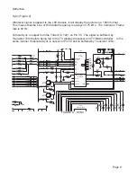
AUXILIARY POWER SUPPLY
1V5
2
G
C
*
0V1
E
0V
B
3V4
3m3
7
3
E
0V7
E
158V
0V
*
E
0V
C
E
B
C
B
3V7
Microcontroller
B
11
*
2V5
C
9V
4m7
A4
15V8
0V6
B
6V
8V1
330K
B
15V8
To 1533 Of
Source
*
*
3V2
0V
C
0V
*
E
B
2V
**
0V
*
D
A4
14
B
0V
E
C
0V
0V7
*
*
*
*
*
*
*
*
0V
B
C
10V7
B
*
C
*
0V
E
B
C
0V6
8V
C
E
9V
*
6V3
*
9530
9534
NAFTA
30WSRF-HD
---
---
---
---
SIZE
3548
3551
3566
4523
4540
4548
4551
4566
4585
5523
6553
7535
9515
9524
9529
---
---
Vaux_GND
+3V3
AUX_ON|ITV_MSG
POWER_DOWN
+8V
+12VA
Vaux_GND
Vaux_GND1
100MHZ 120R
BAS316
SI2307DS-E3
---
---
---
---
---
---
---
---
---
---
---
JMP
---
JMP
---
---
100MHZ 120R
BAS316
SI2307DS-E3
---
---
---
---
---
9534
Vaux_GND1
Vaux_GND
Vaux_GND
7561
I537
3537
68K
PDTC143ZT
I594
I596
6512
BZX384-C18
68K
3546
22u
2510
F578
2591
1n0
470p
2539
3568
47K
1n0
2524
3548
68K
I536
I556
I532
Vaux_GND
3581
22K
I526
BAV21WS
6537
Vaux_GND1
2590
BC847BW
7584
F584
10n
2575
BZX384-C15
6549
BAV21WS
6532
6545
SB340L-7010
2526
100n
1
3
Vaux_GND1
L78L33ACZ
7544
2
10K
3593
1000mA
T
1532
I558
2584
470u
2564
9509
100n
I512
68K
3540
I554
4585
I553
7535
SI2307DS
Vaux_GND
5
6
7
8
16V
47u
2558
1534
1
2
3
4
Vaux_GND
F535
10K
3591
220R
3563
6540
BAS316
4566
2K2
BAW56W
3536
Vaux_GND
2586
330p
9529
BAS316
6531
BC857B
7532
I533
I545
RGP10D
6533
33K
Vaux_GND
5521
3592
IMX1
1
2
MainSupplyGndA
Vaux_GND
7549-2
7
8
9
HEATSINK
0088
1
10
11
12
2
3
4
5
6
1
2
1533
BAS316
6534
3587
2K2
2580
10n
I509
3532
I588
3529
1K2
3560
33R
BC847BW
7577
BAV21WS
6538
3538
Vaux_GND
2523
1n0
I589
6546
STPS10L60D
100n
2543
HEATSINK
0083
1
2
BAS316
6543
5523
4551
I538
I599
I563
I592
3528
4M7
I534
3585
68K
3535
7545
3
1
2
4R7
SI2305DS
3544
2K2
I557
9523
100n
2520
SB340L-7010
6544
7583
BC847BW
5526
IMX1
7549-1
BZX384-C12
Vaux_GND1
3594
6542
4548
22K
3586
5K6
82K
I510
3590
I547
Vaux_GND
Vaux_GND
Vaux_GND
4523
I565
3534
F577
3533
1
4
3
2
7516
TCET1103(G)
Vaux_GND1
Vaux_GND1
Vaux_GND
BZX384-C6V8
6547
3588
470K
1n0
2538
F534
7575
PDTC143ZT
2579
10n
I593
Vaux_GND1
F582
100n
2576
4540
220R
3561
5527
Vaux_GND
9524
3525
47n
2521
2588
2589
2u2
Vaux_GND
1m0
2536
F537
Vaux_GND1
3562
220R
9554
4567
I539
Vaux_GND1
I568
PDTC143ZT
680R
3542
7547
470u
2587
3549
270R
Vaux_GND
Vaux_GND
BC857B
3583
5K6
7585
3596
10K
2525
470p
2585
1u0
470u
2534
16V
BAS316
6554
BAS316
6553
SARS03
6550
2578
1n0
2544
2n2
I540
Vaux_GND1
F581
I595
F585
2582
100n
3527
47K
3565
15K
2546
2u2
Vaux_GND
2557
47u
16V
Vaux_GND1
9515
7567
BC847B
Vaux_GND
3595
100K
7525
10u
2583
3539
1K0
3550
220K
7510
3547
68K
3K3
3567
Vaux_GND
F580
9
2577
100u
10
11
12
2
4
5
6
7
8
SS28411-00
5504
1
3553
27K
3543
10K
STPS10L60D
6552
56K
3530
I590
I529
2528
470n
Vaux_GND
2K2
3545
F586
I528
I531
3589
10K
Vaux_GND1
3551
4R7
1
2
3
MAINSUPPLYGND
1535
6539
SB340L-7010
7576
BC847BW
I560
2535
I597
3526
68K
3566
3597
47K
68p
2592
SI2307DS
7509
5524
10u
9536
2
1
3
3531
1K0
TL431CZ-AP
7542
Vaux_GND1
I530
BAS316
6536
3598
Vaux_GND1
Vaux_GND1
F583
2556
47u
9530
16V
2
1
3
2555
47u
16V
7543
L78L33ACZ
+3V
+5V
+8VA
Stdby_con
+6VA
+5V
+3V3A
+6V
+6VA
VDC
+3V3A
+8V
AC_IN
VCC
+3V3A
B
1.27V On
1.45V Off
15.5 On
11.5 Off
21 On
11.8 Off
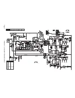
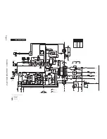
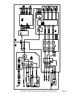
FIGURE 2 - AUXILIAR
Y POWER SUPPL
Y
Page 6
Содержание L05HD
Страница 13: ...FIGURE 5 TV SIGNAL PROCESSOR Page 11 ...
Страница 16: ...FIGURE 7 CONTROL Page 14 ...
Страница 19: ...FIGURE 9 DETAILED VIDEO SIGNAL FLOW BLOCK Page 17 ...
Страница 24: ...FIGURE 13 AUDIO OUTPUT Page 22 ...
Страница 27: ...FIGURE 16 WIRING INTERCONNECT Page 25 ...
Страница 28: ...Page 26 SERVICE POSITION ...
Страница 32: ......


