95
9.3.6.
Test
Item
Operation
Default
Remarks
LED
1. Click
“LED”
on the main menu.
2. Click
“START”
on
“LED”
dialog box to start LED Test
continuously until clicking
“STOP”
.
3. Click
“Close”
to return to the main menu.
—
Each indicator turns on or off
in a constant period.
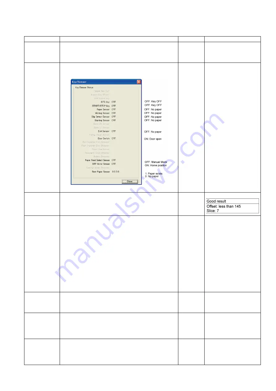
Key / Sensor
1. Click
“Key / Sensor”
on the main menu.
2. Check the key and sensor status on the
“Key / Sensor”
dialog box.
3. Click
“Close”
to return to the main menu.
—
Sensor Sensitive
Level
1. Click
“Sensor Sensitive Level”
on the main menu.
2. Check each sensor’s sensitive level (Offset, Slice) on the
Sensor Sensitive Level
dialog box.
3. Click
“Close”
to return to the main menu.
—
Feed Motor
1. Click
“Feed Motor”
on the main menu.
2. Click
“START”
on the
“Feed Motor”
dialog box to start to
rotate Paper Feed Motor periodically controlled in the
paper-feed direction and its reverse direction until clicking
“STOP”
.
Note:
• Rotating in the paper-feed direction will allow the Paper
Feed Roller Module to go down to perform the paper-feed
function.
• Rotating in the reverse direction will allow the Paper
Feed Roller Module to rise to perform the
paper-separation function.
3. Click
“Close”
to return to the main menu.
—
Conveyor Motor
1. Click
“Conveyor Motor”
on the main menu.
2. Click
“START”
on the
“Conveyor Motor”
dialog box to start
to rotate Conveyor Motor continuously until clicking
“STOP”
.
3. Click
“Close”
to return to the main menu.
—
DFP Pressure
Drive
1. Click
“DFP Pressure Drive”
on the main menu.
2. Click
“START”
on
“DFP Pressure Drive”
dialog box to start
to rotate DFP Pressure Motor continuously until clicking
“STOP”
.
3. Click
“Close”
to return to the main menu.
—
Gate Drive
1. Click
“Gate Drive”
on the main menu.
2. Click
“START”
on the
“Gate Drive”
dialog box to start
to execute the open/close operation of the gate until clicking
“STOP”
.
3. Click
“Close”
to return to the main menu.
—
Содержание KV-S5055C
Страница 3: ...3 15 17 DRIVE Board 244 15 18 POWER Board 247 ...
Страница 8: ...8 3 COMPONENT IDENTIFICATION 3 1 Main Part Names and Locations ...
Страница 9: ...9 ...
Страница 12: ...12 4 2 Included Accessories Confirm that the following items are included with the scanner ...
Страница 22: ...22 5 SECTIONAL VIEW 5 1 Bottom Block ...
Страница 23: ...23 5 2 Back Block ...
Страница 24: ...24 5 3 Upper Block ...
Страница 25: ...25 5 4 Lower Block 5 4 1 Mechanical Parts ...
Страница 26: ...26 5 4 2 Boards ...
Страница 37: ...37 Fig 7 2 2 2 Cleaning Position 1 Rollers ...
Страница 39: ...39 Fig 7 2 2 4 Cleaning Position 3 Reflector Sheets ...
Страница 44: ...44 ...
Страница 45: ...45 ...
Страница 68: ...68 4 While releasing the holder s 3 claws pull out the Ionizer Board ...
Страница 92: ...92 ...
Страница 118: ...118 ...
Страница 119: ...119 ...
Страница 120: ...120 ...
Страница 191: ...191 13 17 2 Back Side 1 6 1 6 1 11 1 2 33 34 1 10 1 4 1 2 1 3 4 1 4 1 2 1 19 18 2 1 19 18 2 1 CL4001 CL4003 CL4002 ...
Страница 196: ...196 14 PARTS LOCATION AND MECHANICAL PARTS LIST ...
Страница 197: ...197 14 1 Exterior ...
Страница 199: ...199 14 2 Main Chassis 1 ...
Страница 201: ...201 14 3 Main Chassis 2 ...
Страница 204: ...204 14 4 Sub Chassis 1 ...
Страница 206: ...206 499 XTW3 6LFJ Screw 644 XYN3 J6FJ Screw Safety Ref No Part No Part Name Description Remarks ...
Страница 207: ...207 14 5 Sub Chassis 2 ...
Страница 209: ...209 14 6 Board Box ...
Страница 211: ...211 14 7 Packing ...
Страница 214: ...214 15 REPLACEMENT PARTS LIST ...


