104
5. Feed
1 While pushing the
“START/STOP Key”
on the Control
Panel, turn on the scanner.
—
—
2 Release the key after LED (Back) status changes to
blinking.
OFF
→
Blinking
3 Push the “
START/STOP Key
” once to enter the test
selection mode.
Blinking
→
Count
4 Push the
“START/STOP Key”
once at the timing when
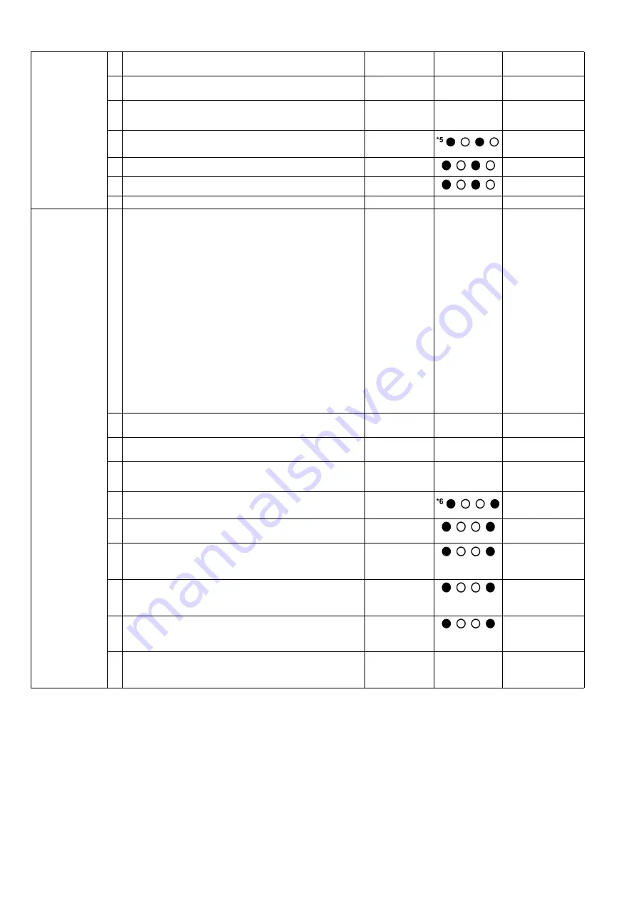
LED (Back) status is 5 (h)
*5
.
5 Set documents on the Feed Tray.
6 Push the
“START/STOP Key”
to feed documents.
7 Turn off the scanner to finish this test.
—
—
6. Shading
1 While pushing the
“START/STOP Key”
on the Control
Panel, turn on the scanner.
—
—
Before executing the
shading function, be
sure to clean the
Scanning Glass (F),
Scanning Glass (B),
Reference Plate (F),
Reference Plate (B),
rollers, and
conveyors related to
conveying
documents.
Until this process
is completed,
don’t stop the
process by
opening any doors
or turning off the
scanner.
2 Release the key after LED (Back) status changes to
blinking.
OFF
→
Blinking
3 Set the Shading Sheet (Part No.: See 14.8.) on the
Hopper in landscape orientation.
OFF
→
Blinking
4 Push the “
START/STOP Key
” once to enter the test
selection mode.
Blinking
→
Count
5 Push the
“START/STOP Key”
once at the timing when
LED (Back) status is 6 (h)
*6
.
6 Push the
“START/STOP Key”
for 5 seconds or more to
start shading.
7 When the Ready and Error Indicators start to blink,
reverse Reference Plates to white after opening the
ADF Door. And then close the ADF Door.
8 Paper feeding starts to execute the shading.
(At this time, the Error Indicator status changes from
blinking to OFF.)
9 When the Ready and Error Indicators start to blink
again, reverse Reference Plates to black after opening
the ADF Door. And then close the ADF Door.
10 After confirming the Ready Indicator turns ON and the
Error Indicator turn OFF, turn off the scanner to finish
this test.
—
Содержание KV-S5055C
Страница 3: ...3 15 17 DRIVE Board 244 15 18 POWER Board 247 ...
Страница 8: ...8 3 COMPONENT IDENTIFICATION 3 1 Main Part Names and Locations ...
Страница 9: ...9 ...
Страница 12: ...12 4 2 Included Accessories Confirm that the following items are included with the scanner ...
Страница 22: ...22 5 SECTIONAL VIEW 5 1 Bottom Block ...
Страница 23: ...23 5 2 Back Block ...
Страница 24: ...24 5 3 Upper Block ...
Страница 25: ...25 5 4 Lower Block 5 4 1 Mechanical Parts ...
Страница 26: ...26 5 4 2 Boards ...
Страница 37: ...37 Fig 7 2 2 2 Cleaning Position 1 Rollers ...
Страница 39: ...39 Fig 7 2 2 4 Cleaning Position 3 Reflector Sheets ...
Страница 44: ...44 ...
Страница 45: ...45 ...
Страница 68: ...68 4 While releasing the holder s 3 claws pull out the Ionizer Board ...
Страница 92: ...92 ...
Страница 118: ...118 ...
Страница 119: ...119 ...
Страница 120: ...120 ...
Страница 191: ...191 13 17 2 Back Side 1 6 1 6 1 11 1 2 33 34 1 10 1 4 1 2 1 3 4 1 4 1 2 1 19 18 2 1 19 18 2 1 CL4001 CL4003 CL4002 ...
Страница 196: ...196 14 PARTS LOCATION AND MECHANICAL PARTS LIST ...
Страница 197: ...197 14 1 Exterior ...
Страница 199: ...199 14 2 Main Chassis 1 ...
Страница 201: ...201 14 3 Main Chassis 2 ...
Страница 204: ...204 14 4 Sub Chassis 1 ...
Страница 206: ...206 499 XTW3 6LFJ Screw 644 XYN3 J6FJ Screw Safety Ref No Part No Part Name Description Remarks ...
Страница 207: ...207 14 5 Sub Chassis 2 ...
Страница 209: ...209 14 6 Board Box ...
Страница 211: ...211 14 7 Packing ...
Страница 214: ...214 15 REPLACEMENT PARTS LIST ...


