2.
Connecting equipment
Depending on the type of TV set, a variety of equipment
can be connected. The exact number of pieces of
equipment depends on the number of connectors on the
back of the TV set
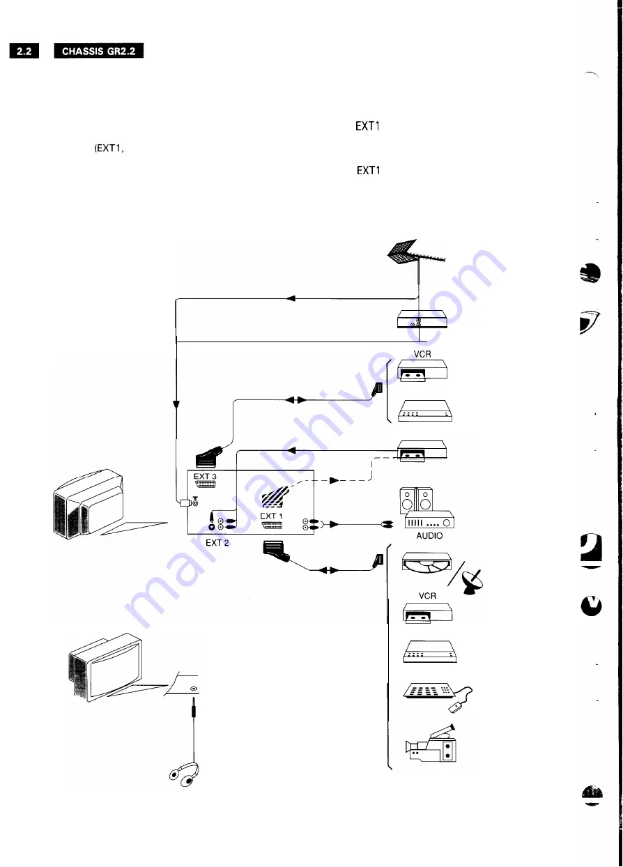
2 or 3). The wiring diagram in
Fig. 2.1 shows which kinds of equipment can be
connected. The wiring diagram shows the TV set with
the maximum number of connectors possible for the
GR2.2 chassis.
An RGB source (e.g. laserdisc player) can only be
connected to
In order to switch the TV set to RGB
operation, this RGB source must generate both a CVBS
status signal at pin 8 and an RGB status signal at pin 16
of the euroconnector. It is not possible to switch the
equipment to
in RGB operation using the remote
control.
CANAL +
S-VHS VCR
PCS 59 734 GB
CANAL +
Fig. 2.1


