Mechanical Instructions
EN 8
FHP PDP
4.
4.1.4
ABUS-L Circuit Board
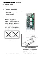
Figure 4-7 ABUS-L board removal (1/2)
Figure 4-8 ABUS-L board removal (2/2)
Remove the circuit board by following the steps below. To
install the circuit board, reverse the removal procedure.
1.
Unplug the connector [1].
2.
Remove the screws [2] fixing the ADMs.
3.
Release the lock of the FPC connectors [3], and remove
the ADM flexible board.
4.
Release the lock of the FPC connector [4] and unplug the
signal cable.
5.
Remove the screws [5] fixing the ABUS-L board.
6.
Remove the ABUS-L board.
7.
When installing the ABUS-L board, put the board in such a
position that it is locked by the tabs [6] before fixing it with
the screws.
4.1.5
ABUS-R Circuit Board
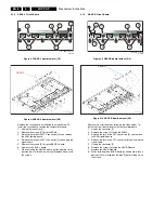
Figure 4-9 ABUS-R board removal (1/2)
Figure 4-10 ABUS-R board removal (2/2)
Remove the circuit board by following the steps below. To
install the circuit board, reverse the removal procedure.
1.
Unplug the connector [1].
2.
Remove the screws [2] fixing the ADMs.
3.
Release the lock of the FPC connectors [3], and remove
the ADM flexible board.
4.
Release the lock of the FPC connector [4] and unplug the
signal cable.
5.
Unplug the connector [5].
6.
Remove the screws [6] fixing the ABUS-R board.
7.
Remove the ABUS-R board.
8.
When installing the ABUS-R board, put the board in such a
position that it is locked by the tabs [7] before fixing it with
the screws.
G_16400_012.eps
310706
4
1
6
6
3
3
2
2
2
2
2
5
5
ABUS-L
G_16400_013.eps
180706
G_16400_014.eps
310706
4
7
7
3
3
1
2
2
2
2
2
6
6
5
ABUS-R
G_16400_015.eps
180706


