Pfaff 3827-4/33 Скачать руководство пользователя страница 35

Sewing

10 - 2

10

.02

Programmed sewing (shoulder seams)

In the programmed sewing mode previously defined seam segments for the shoulder

seams are sewn automatically.
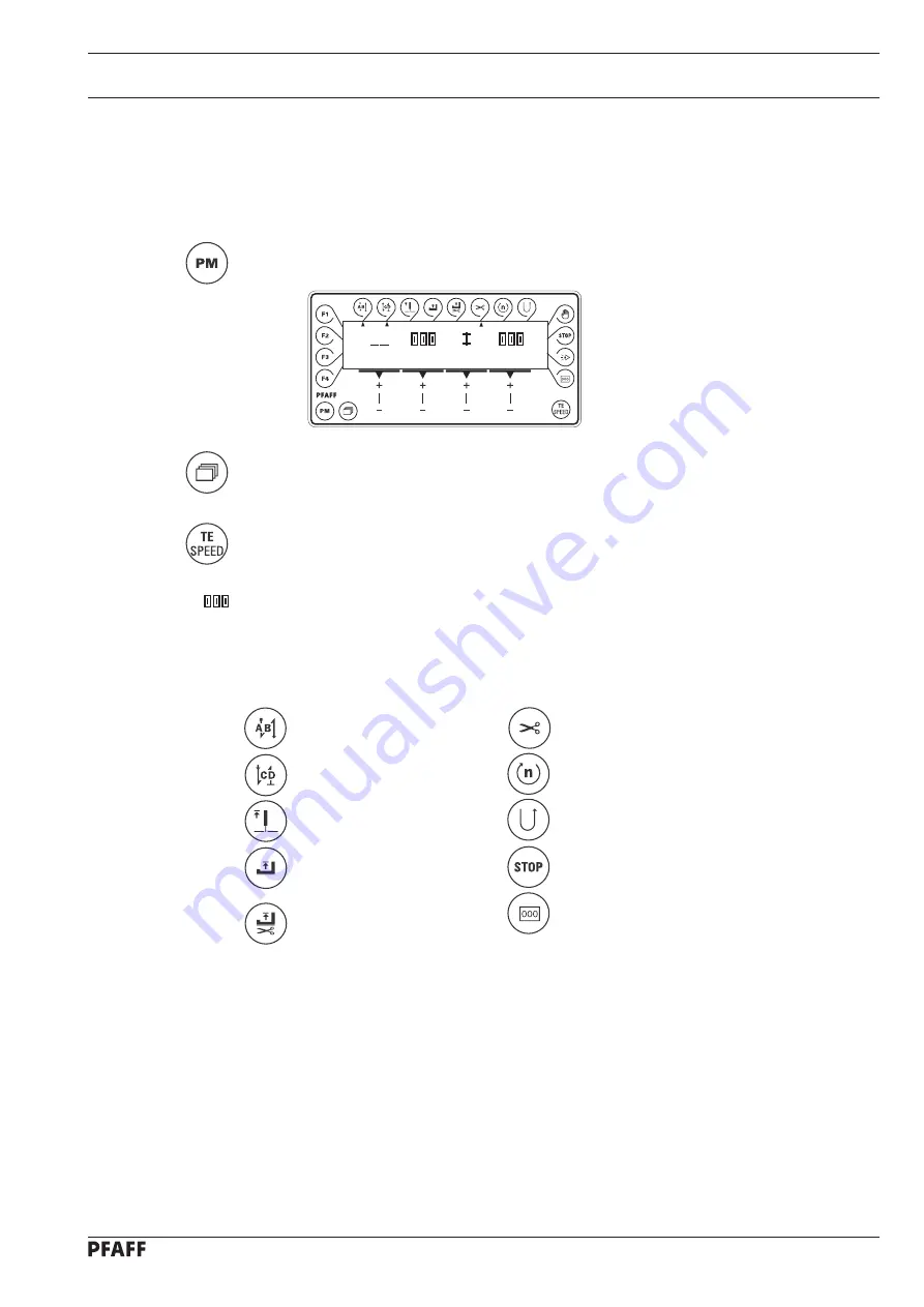
Switch on the machine.

If necessary, call up programmed sewing.

If necessary, change the tack value, also see 

Chapter 9.09 Entering the start and end

backtacks.

If necessary, change the maximum speed, see 

Chapter 9.08 Entering the maximum

speed.

If necessary, change the number of stitches for the fullness with the corresponding

+/- keys

, see 

Chapter 9.07 Pre-selecting the stitch length and fullness

.

Further functions, also see 

Chapter 7.07.02 Function keys:

Start backtacks on/off

Thread trimming on/off

End backtacks on/off

Fixed speed on/off

Needle position raised on/off

Reverse sewing direction on/off

Presser foot raised on/off

Programmed stop on/off

Presser foot raised after

Stitch count on/off

thread trimming on/off

Sewing is carried out with the pedal functions, see 

Chapter 7.02 Pedal.

10

1

3

Содержание 3827-4/33

Страница 1: ...Instruction manual 3827 296 12 18 593 002 Betriebsanleitung engl 02 06 This instruction manual applies to machines from the following serial numbers onwards 2713253 4 33 4 34...

Страница 2: ...cations The reprinting copying or translation of PFAFF Instruction Manuals whether in whole or in part is only permitted with our previous permission and with written reference to the source PFAFF Ind...

Страница 3: ...age 5 1 6 Explanation of symbols 6 1 7 Controls 7 1 7 01 On off switch 7 1 7 02 Pedal 7 1 7 03 Knee switch 7 2 7 04 Keys on the machine head 7 2 7 05 Adjustment lever for stitch length and fullness 7...

Страница 4: ...es 10 6 11 Care and Maintenance 11 1 11 01 Cleaning the machine 11 1 11 02 Oil level of the machine 11 2 11 03 Cleaning lubricating the top feed joints 11 2 11 04 Checking the air pressure 11 3 11 05...

Страница 5: ...1 12 05 29 Limiting the stitch length 12 32 12 06 Adjusting the thread trimmer 900 99 12 33 12 06 01 Lateral adjustment of the thread catcher 12 33 12 06 02 Front reversal point of the thread catcher...

Страница 6: ...ne unattended and during maintenance work the machine is to be separated from the power supply by switching off the On Off switch or by removing the plug from the mains Everyday maintenance work is on...

Страница 7: ...onnel is to be instructed as to the safety equipment of the machine and regarding safe work methods It is the duty of the user to only operate the machine in perfect running order It is the obligation...

Страница 8: ...e which may limit its safety 1 05 02 Specialist personnel Specialist personnel are persons with a specialist education in the fields of electrics electronics and mechanics They are responsible for the...

Страница 9: ...ea while adjusting the machine settings Objects can become trapped or be slung away Danger of injury Do not operate the macine without finger guard 1 Danger of injury by the needle Do not operate the...

Страница 10: ...images On the side seams the fullness to be applied is switched on using a manual switch Any and all uses of this machine which have not been approved of by the manufacturer are considered to be inap...

Страница 11: ...400 VA Fuse protection 1 x 16 A inert Working air pressure 6 bar Air consumption 1 6 l work cycle Noise data Emission sound pressure level at the workplace with a sewing speed of 4000 spm LpA 79 dB A...

Страница 12: ...d various plastic mat erials The electrical equipment comprises plastic materials and copper The machine is to be disposed of according to the locally valid pollution control regula tions if necessary...

Страница 13: ...he machines are only transported in an upright position 5 03 Disposal of packing materials The packing materials of this machine comprise paper cardboard and VCE fibre Proper dis posal of the packing...

Страница 14: ...struction manual work to be carried out or important information is accentuated by symbols These symbols have the following meanings Note information Cleaning care Lubrication Maintenance repairs adju...

Страница 15: ...on the selected functions see Chapter 7 07 Control panel 0 Machine stop 1 Lower presser foot or sewing start 2 Sew 1 Raise presser foot 2 End bartack and trim thread Fig 7 02 0 1 2 1 2 Fig 7 01 7 Cont...

Страница 16: ...wing shoulder seam program Fig 7 03 1 Fig 7 04 2 1 3 7 04 Keys on the machine head Hand button 1 Reset return to semi automatic operation Hand button 2 Turn fullness on and off Hand button 2 Intermedi...

Страница 17: ...stitch length controls 1 and 2 together Pre select fullness with adjustment lever 3 Fig 7 05 3 2 1 Fig 7 06 7 06 Mechanical edge guide PFAFF 3827 4 33 Switching on the edge guide Press knob 1 in the...

Страница 18: ...triangular marking 2 below or next to the respective function key In the sewing mode all relevant sewing data is displayed and these can be changed directly depending on the status of the machine see...

Страница 19: ...s switched on the needle positions at t d c after sewing stops take up lever t d c Foot position after stop If this key is pressed the foot raised after sewing stop function is switched on or off When...

Страница 20: ...nds the sewing mode is selected again If this key is pressed twice within 5 seconds while the machine is in the sewing mode the machine switches to parameter input If this key is pressed once while th...

Страница 21: ...ensure that the stand of the machine is firm and steady also during sewing 8 01 Installation The site where the machine is installed must be provided with suitable connections for elec tric current se...

Страница 22: ...ng the V belt Fit the V belt Loosen nut 1 and tighten the V belt by turning motor mounting 2 Tighten nut 1 8 01 03 Fitting the top V belt guard Fasten bottom section of V belt guard 1 with screws 2 Fa...

Страница 23: ...top 1 is in the slot of synchronizer 3 see arrow Tighten screws 4 just a little Insert the plug for the synchronizer in the socket on the control box Adjust synchronizer 3 see Chapter 12 05 01 Basic p...

Страница 24: ...g 8 06 Connect all plugs as labelled in the control box 1 Screw the earth cable from the sewing head and from main switch 2 to earth point A Connect earth point A and earth point B with earth cable 3...

Страница 25: ...tallation and commissioning 8 5 8 01 07 Fitting the reel stand Fit the reel stand as shown in Fig 8 07 Afterwards insert the stand in the hole in the table top and secure it with nuts pro vided Fig 8...

Страница 26: ...regularities do not operate the machine under any circumstances The machine may only be connected to a grounded socket When the machine is running the balance wheel must turn towards the operator If t...

Страница 27: ...the machine is to be separated from the electricity supply by removing the plug from the mains or switching off the On Off switch 9 01 Inserting the needle Switch off the machine Danger of injury due...

Страница 28: ...it a few times around bobbin 1 in a clockwise direction Switch the bobbin winder on by pushing the bobbin winder spindle 2 and lever 3 simultaneously The bobbin is wound during sewing The tension of...

Страница 29: ...case Lift clip 1 and remove bobbin case 2 Inserting the bobbin case Insert bobbin case 1 until you feel it click into place 9 04 Threading the bobbin case adjusting the thread tension Insert bobbin 1...

Страница 30: ...reading the needle thread Switch off the machine Danger of injury if the machine is started accidentally Thread the needle thread in accordance with Fig 09 05 9 06 Adjusting the needle thread tension...

Страница 31: ...e select the fullness size with adjustment lever 3 Fig 9 07 3 2 1 Press key 4 to set the number of stitches after which the fullness is switched on automatically Press key 5 to set the number of stitc...

Страница 32: ...ey select the desired value for the number of reverse stitches B of the start backtack By pressing the corresponding key select the desired value for the number of reverse stitches C of the end backta...

Страница 33: ...lled screw 1 edge guide switched on To set the large seam depth loosen screws 2 and move stop 3 accordingly edge guide switched off 1 2 2 3 9 10 02 Pneumatic edge guide PFAFF 3827 4 34 Fig 9 09 1 Set...

Страница 34: ...0 3 If necessary change the tack value also see Chapter 9 09 Entering the start and end backtacks If necessary change the maximum speed see Chapter 9 08 Entering the maximum speed If necessary change...

Страница 35: ...ring the maximum speed If necessary change the number of stitches for the fullness with the corresponding keys see Chapter 9 07 Pre selecting the stitch length and fullness Further functions also see...

Страница 36: ...omatically seam segment 1 Press key 2 to set the number of stitches which are still to be sewn with the pre set amount of fullness after the sensor has recognized the edge seam segment 3 The value for...

Страница 37: ...t shoulder seam Insert the workpiece and sew the seam using the pedal function see Chapter 7 02 Pedal Start and end backtacks and thread trimming are carried out automatically Fig 10 02 Operate knee s...

Страница 38: ...houlder seam using the knee switch Press key 1 to set the number of stitches after which the fullness is switched on automatically seam segment 1 Press key 2 to set the number of stitches which are st...

Страница 39: ...ew the seam using the pedal function see Chapter 7 02 Pedal At the end of the seam trigger off the end backtack and thread trimming functions using the pedal see Chapter 7 02 Pedal 10 04 Error message...

Страница 40: ...compartment daily more often if the machine is in continuous use When returning the machine to an upright position make sure that tilt lock 1 is pressed Use both hands to set the machine upright Dange...

Страница 41: ...pecial cleaner part no 99 137 468 91 Afterwards lubricate these points with the special lubricant part no 99 137 467 91 wipe off surplus lubricant with a cloth 11 02 Oil level of the machine Check the...

Страница 42: ...tainer 1 empties itself automatically when the compressed air hose is removed from the air filter regulator Unscrew water container 1 Screw out filter 2 Clean filter 2 with compressed air or isopropyl...

Страница 43: ...to the most logical work sequence for machines which have to be completely adjusted If only specific individual work steps are carried out both the preceding and following chapters must be observed Sc...

Страница 44: ...the handwheel forwards and backwards a little until the rig pin moves into the slot in the crank behind the bearing plate thus blocking the machine Hole 1 0 6 mm after the top dead center of the needl...

Страница 45: ...lay and the pedal functions are blocked to avoid the machine starting accidentally Select mechanic level B see Chapter 12 07 02 Selecting the user level By pressing the corresponding key call up param...

Страница 46: ...mm 12 05 02 Preliminary adjustment of the needle height Requirement With the needle bar at b d c the distance between bottom edge of the needle bar and the needle plate must be16 5 mm Adjust needle b...

Страница 47: ...e needle hole Loosen screws 1 2 and 3 Adjust the needle bar frame 4 both crosswise and in the direction of sewing according to the requirement and tighten screw 2 slightly and screw 3 With screw 1 dra...

Страница 48: ...og when the balance wheel is turned Loosen screw 1 nut 2 Set stitch length at 0 Turn eccentric bush 3 screw 4 so that the marking is pointing downwards and the surface of eccentric bush 3 is at an ang...

Страница 49: ...t With the maximum stitch length set and the needle bar positioned 0 6 mm past t d c adjustment hole 1 the bottom feed dog should not move when the reverse feed key is operated Bring needle bar to 0 6...

Страница 50: ...Requirement 1 With the needle bar set 0 6 past t d c adjustment hole 1 and the stitch length set at 0 the bottom feed dog should be at the top of its stroke 2 The cutout of eccentric 1 should be more...

Страница 51: ...og should be in the centre of the needle plate cutout as seen from the side and in the direction of feed 2 The bottom feed dog should be at the top of its stroke and its entire length should be positi...

Страница 52: ...ew on gauge foot 1 part no 61 111 639 20 and lower it down to touch the needle plate Push out bolt 2 screw 3 and remove connection element 4 from the yoke of lever 5 By turning the balance wheel bring...

Страница 53: ...t and lower it down to touch the needle plate Adjust presser foot screw 9 at the side so that the edge of the presser foot is parallel to the bottom feed dog Lower lifting piece 10 as far as possible...

Страница 54: ...When adjustment foot 1 part no 61 111 639 20 is resting on the needle plate stop 4 should be touching screw 2 Remove presser foot Attach adjustment foot 1 part no 61 111 639 20 and lower it onto the n...

Страница 55: ...ve freely if necessary adjust lever 2 Align top feed dog in the centre of the presser foot cutout in the direction of sewing screw 5 Loosen screw 7 Align the hole of lever 8 with the elongated hole of...

Страница 56: ...p feed dog Requirement When the stitch length is set at 0 and with the adjustment gauge 4 fitted there should be no feeding motion of the top feed dog Set stitch length at 0 While continuously turning...

Страница 57: ...n the needle bar is positioned 0 6 mm past t d c adjustment hole 1 and the maximum stitch length is set lever 3 should not move when the feed reverse key is operated While continuously operating the f...

Страница 58: ...equirement With the needle bar positioned 0 6 past t d c adjustment hole 1 there must be a distance of approx 16 5 mm between the eye of the linkage rod 2 and machine case 3 Bring needle bar to 0 6 pa...

Страница 59: ...er the presser foot 1 onto the needle plate Set stitch length at 3 By turning the balance wheel bring top feed dog 2 to its t d c Turn eccentric pin 3 screw 4 so that its greatest eccentricity points...

Страница 60: ...Requirement When the stitch length is set at 3 and with adjustment gauge 3 fitted the top feed dog should rest on the ascending bottom feed dog when this reaches the top edge of the needle plate Set...

Страница 61: ...2 1 12 05 16 Position of the top feed dog Requirement With the bottom feed dog at its top point of reversal the top feed dog must be parallel to the bottom feed dog Turn eccentric pin 1 screw 2 in ac...

Страница 62: ...h adjustment Requirement When set at 3 the stitch length must be the same size when sewing forwards or in reverse Loosen screw 1 Adjust bush 2 according to the requirement Take care that the eccentric...

Страница 63: ...h and top feed dog stroke adjustment levers all at 3 the top feed dog and the bottom feed dog must work with the same feed motion when the handwheel is turned Set adjustment lever 1 at 3 Push adjustme...

Страница 64: ...ly on the spinning disc 4 and the point of the hook is positioned towards the centre of the needle there must be a clearance of 0 05 0 1 mm between the point of the hook and the needle groove 3 Gear 5...

Страница 65: ...le 4 1 The point of the hook should be in centre of the needle and the top edge of the needle eye should be 0 8 mm below the hook point 2 There should be a clearance of 0 5 mm between the lug of posit...

Страница 66: ...ener height Requirement When bobbin opener 3 is at its left point of reversal the top edge of its finger should be 0 5 mm above the bottom edge of the bobbin case cam Loosen screw 1 Adjust bobbin open...

Страница 67: ...5 must be 0 8 mm 2 When the bobbin opener 3 is at its left point of reversal the bobbin case base 5 should be deflected by approx 0 3 mm by the retaining finger and screw 1 should be resting on stop...

Страница 68: ...rement When the needle bar is positioned 1 8 mm past b d c the bobbin opener 3 should be at its right point of reversal Adjust bobbin opener eccentric 1 screws 2 according to the requirement For bette...

Страница 69: ...ead tension release Requirement When the hand lever 1 is raised the tension discs should be at least 0 5 mm apart Adjust tension release clip 2 screw 3 according to the requirement Lower the presser f...

Страница 70: ...thread check spring 3 must be finished when the needle point enters the material spring path approx 7 mm Adjust thread tension 1 screws 2 according to the requirement The path of thread check spring 3...

Страница 71: ...engaged friction wheel 3 must not rest on drive wheel 1 2 The bobbin winder should switch itself off when the thread is approx 1 mm from the edge of the bobbin Raise hand lever and switch on bobbin wi...

Страница 72: ...feed dog in relation to the sewing foot Requirement When the take up lever is at its t d c the teeth of the top feed dog should not be below the presser foot shoe when the presser foot is raised Adju...

Страница 73: ...8 1 2 ca 12 mm 12 05 28 Top feed dog and sewing foot pressure Requirement Even at top speed the material must be fed perfectly No pressure marks should appear on the material Adjust screws 1 and 2 acc...

Страница 74: ...assembly hole or screw it out according to the limit to be set Set the stitch length control lever 2 at the desired maximum stitch length Set the limiting angle 3 from above so that it touches the con...

Страница 75: ...isconnect the thread trimmer from the pneumatic network and dismantle the needle plate and feed dog Position the needle bar at BDC Push aside catcher stop 1 screws 2 Position the tip of thread catcher...

Страница 76: ...edge of the thread catcher cutout should be positioned 1 to 1 5 mm in front of the front edge of the bobbin case position finger 7 Position needle bar at TDC Position end faces of piston rod 1 and nut...

Страница 77: ...een the front edge of the knife 1 and the needle should be 4 mm On needle feed machines set the stitch length to O Position the needle bar at BDC Align knife 1 screw 2 in accordance with the requireme...

Страница 78: ...f thread catcher 1 Carry out the trimming process manually If both threads are not trimmed in accordance with the requirement loosen screws 2 and adjust thread catcher 1 screws 2 with respect to the k...

Страница 79: ...e tip of trip 4 is at the highest point of the control cam 5 the tension disks must be a minimum of 0 5 mm from each other Push in piston rod 1 manually as far as possible Adjust the distance between...

Страница 80: ...ds of connecting rod 5 off the ball pins on the trimming and control units and remove connecting rod 5 Unscrew the three retaining screws of the control unit and lift off the complete unit To remount...

Страница 81: ...ctions are blocked to avoid the machine starting accidentally Select the desired parameter e g 111 light barrier compensation stitches by pressing the corresponding plus minus key With the correspondi...

Страница 82: ...o VAL 798 0 TE Press the TE Speed key to take over the value and change to the sewing mode When the main switch is switched off the machine changes automatically to user level A VAL No VAL 101 OFF TE...

Страница 83: ...tch size 113 Start with light barrier B C OFF ON OFF ON only when light barrier is dark OFF also when light barrier is light 116 Number of soft start stitches soft start A B C 0 30 0 117 Speed for sof...

Страница 84: ...e 0 100 power 584 Backtack B C OFF ON OFF ON four times OFF double 585 Speed limitation B C 300 4800 1200 6 605 Actual value on display 725 B C OFF ON OFF ON yes OFF no 606 Speed Level 1 min B C 30 30...

Страница 85: ...read take up lever raised 706 Needle position 6 B C 0 255 127 start trimming signal 2 pneumatic thread trimmer 707 Needle position 9 B C 0 255 140 start thread tension release start thread catcher 710...

Страница 86: ...A B C 0 20 0 0 operator level A 1 mechanic level B 11 service level C 799 Selected machine class C 1 1 8 800 Direction of motor rotation viewed from C 0 1 1 V belt pulley 0 left hand rotation 1 right...

Страница 87: ...ter Setting range Set value User lever Description 12 08 Explanation of the error signals Signal Description E001 Pedal not in neutral position E009 Start inhibitor during standstill E010 Incorrect ma...

Страница 88: ...hapter 12 07 02 Selecting the user level Select parameter 797 and set it at ON by pressing the appropriate key The first test block appears on the display The next test blocks can be selected by press...

Страница 89: ...lue transmitters The functions allocated to the inputs displayed can be found in Chapter 12 10 Connection plan for the X5 plug It is possible to move to all 16 switch levels by operating the pedal If...

Страница 90: ...e of the thread monitor is shown here in FW 0 Thread monitor Analogue value of the thread monitor 12 09 08 Test block 7 data transfer With the B key all data is transferred from the control unit to th...

Страница 91: ...14 15 16 17 18 19 20 21 22 23 25 26 27 28 29 30 31 32 33 34 35 36 37 0V 24 24V 5V E3 E6 S1 X7 4 5 X7 1 X7 2 A1 S2 Y1 A4 0V 15V 24V 24V Y4 A5 Y5 Y8 A8 A10 Y2 A2 A3 Y3 S4 S6 S3 X7 3 X7 6 OTE 2 5 3 1 OT...

Страница 92: ...6 25 3x 91 000 407 15 2x 13 Wearing parts This is a list of the most important wearing parts A detailed parts list for the complete machine is included with the accessories In case of loss the parts l...

Страница 93: ...Wearing parts 13 2 11 108 087 15 91 171 854 15 91 171 853 15 91 108 222 15 91 171 850 91 91 165 505 05 11 108 084 15 2x 99 137 151 45 91 171 049 05 91 171 042 05 95 774 464 25 91 700 996 15...

Страница 94: ...14 1 Pneumatics switch diagram Version 10 01 03 91 196 266 95 14 Schaltpl ne PFAFF 3827 2 24 2 34 Automatic presser foot lift Backtacking mechanism Differential adjustment Thread trimmer Edge guide...

Страница 95: ...transmitter Synchronizer PD3 X2 1 Incremental transmitter sewing motor X2 2 Synchronizer PD3 X3 Pedal speed control unit X3 1 S2 Reset X4 Control panel BDF S2 X5 Outputs Inputs X5 1 Y5 Backtacking me...

Страница 96: ...14 3 Circuit diagrams Version 10 01 2006 91 191 497 95 Page 1...

Страница 97: ...14 4 91 191 497 95 Page 2 Version 10 01 2006 Circuit diagrams...

Страница 98: ...14 5 Circuit diagrams Version 10 01 2006 91 191 497 95 Page 3...

Страница 99: ...Notes...

Страница 100: ...n AG Postfach 3020 D 67653 Kaiserslautern K nigstr 154 D 67655 Kaiserslautern Telefon 0631 200 0 Telefax 0631 17202 E Mail info pfaff industrial com Gedruckt in der BRD Printed in Germany Imprim en R...

Отзывы: