Adjustment
35
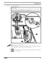
Increase the presser foot pressure somewhat on screw
1
(nut
2
).
Lower the presser foot onto the needle plate.
Position the eccentricity of pin
3
(screw
4
) facing the needle bar.
Position the eccentricity of pin
4
(screw
6
) facing downwards.
Turn the balance wheel until link
7
is in its far rear position.
Push lever
7
(screw
8
) down and insert the corresponding feeler gauge (see Require-
ment) between the vibrating presser and the needle plate.
If fi ne adjustment is required, turn eccentric pin
5
(screw
6
) accordingly.
Fig. 13 - 30
13
.05.27
Vibrating presser clearance
Requirement
When the presser foot is touching the needle plate and the vibrating presser is at top dead
centre, depending on the top feed version, with the stitch length set at
“0”
there should
be the following clearance between the needle plate and the vibrating presser:
1.3 mm
when the vibrating presser is operating behind the needle
2.0 mm
when the vibrating presser is operating in front of the needle (PFAFF 3806-12/22)
3.2 mm
when the vibrating presser is operating in front of the needle (PFAFF 3806-12/23)
When sewing thin materials, on machines with the vibrating presser operating
in front of the needle, the top feed stroke can be limited to
2.0 mm
by pushing
bolt 9 (nut 10) up as far as possible.
3
4
6
5
7
8
1
2
9
10
Содержание 3806-12/22
Страница 49: ...Notes ...


