background image

Adjustment

30

Fig. 13 - 25

13

.05.23 

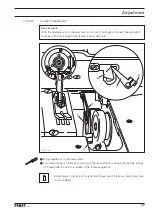
Clearance between presser foot and needle plate

Requirement

With the presser bar lifter 

1

 raised, there must be a clearance of 

7 mm

 between the pres-

ser foot and the needle plate.

1


Place the presser foot on the stitch plate using hand lever 

1

.


Reduce the pressure on the push rod by unscrewing the regulating screw 

2

 (knurled nut 

3

).


Loosen screw 

4

, push out bolt 

5

 and pivot connecting link 

6

 out of the fork of lever 

7

.


Move lever 

8

 to its outer turning point by turning the handwheel.


Push setting gauge 

9

 (order no .: 

61-111 642-19

) under the presser foot and adjust accor-

ding to the 

requirement

.


Loosen screw 

10

 and push out bolt 11

.


Loosen screw 12.


Align the presser foot sideways so that the presser foot edge is parallel to the stitch plate 
cutout.


Bring lifting piece 

13

 down and tighten screw 12.

Screws

 4

 and 

10

 remain loosened for subsequent adjustment.

12

11

7

6

2

3

13

8

1

3

4

7 mm

4

5

6

7

7

9

11

10

Содержание 3806-12/22

Страница 1: ...ADJUSTMENT MANUAL 296 12 19 448 002 Justieranleitung engl 04 2020 This instruction manual applies to machines from the serial number 2 829 139 and software version 0435 008 onwards 3806 12 22 12 23 ...

Страница 2: ...of PFAFF AdJustment Manuals whether in whole or in part is only permitted with our previous authorization and with written reference to the sour ce PFAFF Industriesysteme und Maschinen GmbH Hans Geiger Str 12 IG Nord D 67661 Kaiserslautern ...

Страница 3: ...oiding motion 16 13 05 11 Looper motion 17 13 05 12 Looper height and looper angle 18 13 05 13 Looper to needle clearance in sewing direction 20 13 05 14 Looper to needle clearance crosswise to sewing direction 21 13 05 15 Final adjustment of the needle height 22 13 05 16 Height of rear needle guard 23 13 05 17 Clearance between rear needle guard and needle 24 13 05 18 Guard of looper avoiding mot...

Страница 4: ...9 13 06 Adjusting the top knife chain cutter 40 13 06 01 Agjusting the diagonal position of the knife quide 40 13 06 02 Adjusting the height of the top knife 41 13 06 03 Adjusting the top knife to the stationary knife 42 13 06 04 Changing the top knife 43 13 07 Adjusting the light barrier 44 13 08 Parametereinstellungen 46 13 09 Internet Update der Steuerung P40 CD 46 14 Stromlaufpläne 47 ...

Страница 5: ...ific individual work steps are carried out both the preceding and following chapters must be observed Screws nuts indicated in brackets are fastenings for machine parts which must be loosened before adjustment and tightened again afterwards 13 01 Tools gauges and other accessories for adjusting Screwdrivers with blade width from 2 to 10 mm Spanners wrenches with jaw width from 7 to 14 mm 1 set All...

Страница 6: ... required postion Insert the adjustment pin into the appropriate adjustment hole and apply pressure Turn the balance wheel slightly backwards and forwards until the adjustment pin slips into the rear crank recess blocking the machine Adjustment hole 1 top dead center of the needle bar TDC Adjustment hole 3 bottom dead center of the needle bar BDC Adjustment hole 4 0 8 mm before the top dead center...

Страница 7: ...ate must be ap prox 0 8 mm Loosen screws 1 2 3 and 4 Shift needle bar frame 5 according to the requirements Tighten screw 3 securely and slightly tighten screw 2 Using screw 1 pull the guide stud behind it against the eye of the needle bar frame 5 and tighten it Loosen screw 2 and turn the balance wheel a few times this helps to avoid the oc curence of any tension Tighten screw 2 Tighten screw 4 m...

Страница 8: ...ent of the needle height Requirement With the needle bar at TDC pin in hole 1 the needle point must be positioned 11 mm above the needle plate Bring the needle bar 1 to TDC Adjust needle bar 1 screw 2 according to the requirement Fig 13 03 1 2 11 mm ...

Страница 9: ...ne readjustment see chap 13 05 36Top feed synchronous position Insert a suitable pin or Allen key into the hole 5 of the clamping ring 6 and hold the shaft 7 with it Turn shaft 7 screw 8 according to the requirement Fig 13 04 5 6 8 7 45 2 3 4 1 13 05 03 Zeroing the bottom feed on machines with closed gearcase Requirement With the stitch length set at 0 the feed dog must not move when the balance w...

Страница 10: ...gth adjusting lever 1 all the way down Set stitch length at 0 Turn eccentric bush 2 screw 3 so that the marking faces downward and the surface of the eccentric bush 2 is at an angle of 45 to the front edge of the machine readjustment see chap 13 05 36Top feed synchronous position While turning the balance wheel continuously twist crank 4 screw 5 according to the requirement Fig 13 05 4 5 45 2 3 4 ...

Страница 11: ...uld be on when tapped have little play approx 0 3 mm Loosen screws 1 and 2 Taking care that the stitch changeover button 3 is in contact with the stop 4 place the driver lever 5 lightly against the stitch changeover button and tighten screw 1 Screw 2 remains until the top feed zero position is set Chap 13 05 31 still solved Fig 13 06 1 2 3 5 4 ...

Страница 12: ... mm before TDC pin in hole 4 the feed dog must not move when the reverse feed switch is operated Loosen screw 1 Position needle bar 0 8 mm before TDC and adjust stitch length to maximum setting While operating the reverse feed switch twist eccentric 2 until the slot is visible see ar row and crank 3 does not move Tighten screw 1 2 1 3 4 1 3 ...

Страница 13: ...tting gauge over its entire length Set the maximum stitch length and position the needle bar appropriately Place the adjustment gauge Order No 61 111 642 19 on the needle plate so that its recess is centered above the feed slots arrow pointing in feed direction and lower the presser foot Loosen screws 1 and 2 By turning cranks 3 and 4 and the eccentric sleeve 5 adjust the feed dog according to the...

Страница 14: ... at TDC pin in hole 1 the slot of eccentric 2 must be pointing vertically Loosen screw 1 Position needle bar appropriately Twist eccentric 2 according to the requirement and tighten accessible screw 1 By turning the balance wheel make the second screw 1 accessible and tighten it 1 2 1 3 4 ...

Страница 15: ...of 1 5 mm should be set 2 With the maximum stitch length setting the feed dog must not bump into the stitch plate cutout Set limit lever 3 to the desired maximum stitch length Set stitch adjusting levers 4 and 5 to the desired stitch length Turn screw 1 nut 2 according to requirement 2 According to requirement 1 fix it in this position with screw 7 and nut 8 1 2 3 4 5 7 8 6 ...

Страница 16: ...t TDC pin in hole 4 the slot in eccentric 2 must be positioned ex actly under the center of the shaft Loosen screw 1 Bring the needle bar into the appropriate position Turn eccentric 2 according to the requirement Tighten screw 1 When tapping the hook must press the needle slightly 1 2 1 3 4 ...

Страница 17: ...alance wheel until the point of the looper advancing from the right is at the right hand side of the needle In this position attach C clamp order No 61 111 600 35 001 to the needle bar so that the upward motion of the needle bar is blocked Turn the balance wheel in the opposite direction until the C clamp regains contact In this position the looper point must be at the left hand side of the needle...

Страница 18: ...ition 1 depending on the machine type there must be a clearance as indicated in the table below between the highest point of the looper back and the needle plate rest and 2 the looper 7 surface of the looper with the thread groove should be at an angle of 4 to the imaginary centre line of the bedplate with needle size 90 3 Fig 13 13 4 5 7 8 8 8 1 X 6 2 4 ...

Страница 19: ...st eccentric bearing stud 3 screws 4 and 5 according to requirement 1 Check the adjustment If the required clearance is not obtained replace spacer 6 In order to do so looper 7 screw 8 has to be removed Looper 7 screw 8 set according to requirement 2 Spacer Order No Spacer Order No 0 3 mm 91 170 693 05 0 8 mm 91 169 615 05 0 5 mm 91 169 614 05 1 2 mm 91 170 694 05 ...

Страница 20: ...rn the balance wheel until the looper point coming from the right reaches the left side of the needle Align looper unit 1 screw 2 according to the requirement If a clearance of 0 1 mm cannot be obtained the setting of the eccentric bea ring stud 3 can be corrected In this case the looper height and angle must be checked see Chapter 13 05 12 Looper height and looper angle 1 2 2 2 0 1 mm 3 ...

Страница 21: ...rning the balance wheel bring the looper 1 to its right point of reversal Place the 3 6 blade of looper gauge 2 Order No 61 111 643 06 against the needle 3 with its notch facing the direction of feed Make sure that the driving link 4 is vertical and turn the ball pin 5 screw 6 with the aid of an open ended spanner size 6 until the looper point 1 contacts the blade With highly elastic threads the d...

Страница 22: ...aches the left side of the needle the top edge of the needle eye must be 1 0 1 2 mm below the bottom edge of the looper Turn the balance wheel until the looper point which is coming from the right reaches the left side of the needle Without turning the needle bar 1 screw 2 adjust it according to the requirement Fig 13 16 2 1 1 0 1 2 mm ...

Страница 23: ...guard Requirement When the needle bar is at bottom dead center pin in hole 3 the vertical surface of the needle guard 1 must cover about 2 3 of the needle eye Bring the needle bar to BDC Adjust needle guard 1 screw 2 according to the requirement 1 2 1 3 4 1 ...

Страница 24: ...rom the right reaches the right side of the needle the needle guard 3 must still be in slight contact with the needle Turn the balance wheel until the looper point is located at the right side of the needle Adjust bracket 1 screw 2 according to the requirement Under no circumstances should the needle be deflected by the needle guard 3 1 2 3 ...

Страница 25: ...g 13 20 13 05 18 Guard of looper avoiding motion eccentric Requirement During motion the eccentric 3 must not touch guard 1 Adjust guard 1 screws 2 accessible through adjustment holes according to the requirement 2 3 1 ...

Страница 26: ...2 and the needle bar frame 3 2 The take up lever 2 must be able to move freely in the center of the needle head slot and must not have any contact either at TDC or BDC By turning the handwheel make screw 1 accessible and loosen it slightly Bring needle bar to BDC Adjust take up lever 2 according to requirement 1 Tighten screw 1 in compliance with requirement 2 1 3 4 Fig 13 21 ...

Страница 27: ... The thread guide 2 must be vertical and attached with a screw in max down of the elongated hole Bring the needle bar to bottom dead center After loosening the screw adjust the needle thread regulator 1 according to requirement 1 Tighten the screw of the needle thread regulator Align thread guide 2 screw 3 according to requirement 2 Depending on the type of material and thread used the basic setti...

Страница 28: ...e plate edge guide must be 29 mm 2 The front edges of the thread take up device 3 and the thread regulator 1 must be about 8 mm apart Adjust thread regulator 1 screws 2 according to requirement 1 Adjust thread take up device 3 screw 4 according to requirement 2 Depending on the type of material and thread used the basic setting may have to be modified 5 1 3 4 2 29 mm 8 mm 5 1 3 4 ...

Страница 29: ... 1 are in the middle of the thread regulator 3 Depending on the type of material and thread used the basic setting may have to be modified 13 05 22 Looper thread puller Requirement With the needle bar in top dead center pin in hole 1 both eyes of looper thread puller 1 must be at the front edge of the thread take up device 4 Fig 13 24 1 3 1 3 4 2 1 4 2 ...

Страница 30: ...osen screw 4 push out bolt 5 and pivot connecting link 6 out of the fork of lever 7 Move lever 8 to its outer turning point by turning the handwheel Push setting gauge 9 order no 61 111 642 19 under the presser foot and adjust accor ding to the requirement Loosen screw 10 and push out bolt 11 Loosen screw 12 Align the presser foot sideways so that the presser foot edge is parallel to the stitch pl...

Страница 31: ...ne cessary re position or set lever 8 Insert pin 10 with its eccentric lobe facing downwards into the holes of levers 9 and 8 and tighten screw 11 Move lever 12 to its outermost position Push lever 8 in feeding direction until you feel it move into contact and tighten screw 7 Position the vibrating presser crosswise so that it does not touch the lifting presser screw 13 Tighten screw 13 13 05 24 T...

Страница 32: ...nd top feed set at 0 and with adjustment link 9 fi tted drive lever 22 must not make any movement when the balance wheel is turned Raise the presser foot Loosen screws 1 2 and 3 Set crank 4 parallel with crank 5 and tighten screw 2 1 9 10 2 5 4 17 18 Fig 13 27 14 13 16 22 8 7 6 21 20 3 19 ...

Страница 33: ...so adjust lever 16 screw 15 so that the vibrating presser no longer moves Bring the tie rod 14 in the middle of the slot and tighten the nut 13 Set feed regulator levers 6 7 and 8 at 3 Move crank 17 axially and radially against crank 18 and tighten screw 1 Remove adjustment link 9 Push feed regulator levers 6 7 and 8 fully to the top Set a clearance of 0 5 mm between reverse feed lever 21 and actu...

Страница 34: ...ot is pointing towards the operator and lever 3 does not move 13 05 26 Feeding motion of the top feed dog Requirement When the needle bar is positioned 0 8 mm past t d c adjustment hole 4 and the maximum stitch length is set lever 3 should not move when the feed reverse key is operated Fig 13 29 1 2 1 3 4 3 ...

Страница 35: ...ating presser clearance Requirement When the presser foot is touching the needle plate and the vibrating presser is at top dead centre depending on the top feed version with the stitch length set at 0 there should be the following clearance between the needle plate and the vibrating presser 1 3 mm when the vibrating presser is operating behind the needle 2 0 mm when the vibrating presser is operat...

Страница 36: ...rding to the requirement 13 05 28 Vibrating presser lifting motion Requirement The top feed dog should touch the bottom feed dog see arrow if with stitch length set ting 2 the lower feed dog has reached the top edge of the needle plate Fig 13 31 2 1 ...

Страница 37: ... 37 Turn eccentric bolt 1 screw 2 according to the requirement 13 05 29 Position of vibrating presser Requirement When the feed dog is at its highest the vibrating presser must be set parallel to it 2 1 Fig 13 32 ...

Страница 38: ... screw 2 in the slot according to the requirement and tighten nut 1 Fig 13 33 1 2 13 05 30 Eliminating diffences in feed stroke lengths Requirement When the stitch length and top feed feed levers are set to 3 should work with the same feed when turning the handwheel upper and lower feed ...

Страница 39: ...ure marks may appear on the material Top feed pressure Set regulating screw 1 flush with the top edge of the housing Presser foot pressure Turn regulating screw 2 knurled nut 3 until there is a distance of approx 27 mm between its collar and the machine housing The pressure on the top feed and presser foot can be increased or reduced if necessary Fig 13 35 27 mm 3 2 1 ...

Страница 40: ... wheel until the feed dog 7 is at its highest point Push knife 6 downwards as far as it will go and make sure that it canmove freely in the needle plate Align the knife guide 1 to the throat plate edge on the right so that the distance is 0 2 mm On subclass 12 22 set the top knife 6 guide lug as to the knife 6 as possible about 0 2 mm without actually touching it On subclass 12 23 adjust the top k...

Страница 41: ... be about 0 5 mm be low that of the stationary knife 2 Fig 13 37 Loosen the screws 3 Push knife 1 downwards as far as it will go Position the cylinder bracket so that the right cutting edge of the top knife 1 protrudes 0 5 mm below the stationary knife 2 Tighten the screws 3 Top knife 1 must still move freely in the needle plate cutout 1 1 2 3 ...

Страница 42: ...top knife 1 must not strike the stationary knife Turn the balance wheel Top knife 1 must not touch any of the feed parts when in its bot tom position Carry out a cutting test by hand with thread chain and pieces of bridle tape The knife must cut perfectly across its entire cutting edge Refit photo cell bracket 3 with screws 2 and position it according to see Chapter 13 07 Setting the photocell Rei...

Страница 43: ...g 3 On subclass 12 23 screw 1 and 4 are situated at the rear side of knife bracket 6 Take out screws 4 and remove top knife 5 Insert a new top knife 5 Tighten screws 4 Check the knife height according to see Chapter 13 06 02 Adjusting the height of the top knife and adjust if necessary Replace spring 3 and chain nipper 2 and tighten screw 1 again Reconnect the compressed air Machine switched on Fi...

Страница 44: ...2 Light barrier compensation Without underlying material Move the sensor 1 to static teach in mode to do this press the key 4 for approx 2 seconds until the LED 5 flashes green Press the key 4 on the sensor 1 briefly sensor ON position After 5 sec Place material underneath and press button 4 briefly Sensor is in the OFF po sition LED 5 lights up green until the LED goes out green Remove material W...

Страница 45: ...parator X3 pin 27 t 51 54 0 35 30 Setting the output function for the output machine connector pin 27 unroller t 22 00 0 3 2 Rollout mode 0 OFF 1 Seam end 2 Seam beginning 3 Start of seam end of seam t 22 03 0 255 3 Number of stitches until the chain separator is raised at the beginning of the seam Thread cutter chain separator t 02 10 0 359 150 Switch on angle t 08 12 t 02 10 t 02 11 t 02 11 0 35...

Страница 46: ...der Steuerung P40 CD sowie PC Tool DongleCopy kann unter der Internet Adresse https partnerweb pfaff in dustrial com herruntergeladen werden 13 09 Internet Update der Steuerung P40 CD Um ein Steuerungsupdate durchführen zu können benötigt man ein Dongle mit entspre chender Maschinensoftware Einen leeren Dongle kann man unter der Bestellnummer 72 250 303 91 erhalten Um Software auf den Dongle zu la...

Страница 47: ...B PH IND VCC VCC GND WT BN shield 1 2 3 4 5 9 BN YE GY WH GN 1 2 3 4 5 PE U V W 1 2 3 4 5 GN YE BN BK BU 1 2 3 4 1 shield Ground 2 3 4 5 n c n c 3 3V SDA n c n c SCL GND 6 7 8 IN EXT1 IN EXT2 IN EXT3 IN EXT4 N C IN EXT5 1 2 3 4 5 6 shield 7 8 9 IN EXT6 24V GND N C CAN L GND N C N C N C 1 2 3 4 5 6 shield 7 8 9 CAN H 24V N C E M M1 1 M1 Sewing Motor Nähmotor ID CAN ...

Страница 48: ...ik 3 3V 6 7 8 9 10 11 12 13 14 15 16 17 18 19 24V magn GND 24V stab 20 21 22 23 24 25 26 27 28 29 30 31 32 33 34 24V magn 35 36 37 1 20 19 37 1 5 6 9 180 5V 0V shield SYNC function control box P40 CD input manuel backtack 5 input mount thread 6 input invers backtack 14 output led 31 OV 19 24V only inputs 16 light sensor in 13 24V power 17 free 33 output sucker trimmer 27 output backtack 34 output ...

Страница 49: ...Notes ...

Страница 50: ...an authorized licensee of the PFAFF trademark PFAFF Industriesysteme und Maschinen GmbH Hans Geiger Str 12 IG Nord D 67661 Kaiserslautern Telefon 49 6301 3205 0 Telefax 49 6301 3205 1386 E mail info pfaff industrial com Gedruckt in der BRD Printed in Germany Imprimé en la R F A Impreso en la R F A ...

Отзывы: