background image

Safety

1 - 1

1

Safety

1

.01

Directives

This machine is constructed in accordance with the European regulations contained in the

conformity and manufacturer’s declarations.

In addition to this Instruction Manual, also observe all generally accepted, statutory and

other regulations and legal requirements - also those of the country in which the machine

will be operated - and all valid environmental protection regulations!

The regionally valid regulations of the social insurance society for occupational accidents or

other supervisory organizations are to be strictly adhered to!

1

.02

General notes on safety

This machine may only be operated by adequately trained operators and only after having

completely read and understood the Instruction Manual!

All Notes on Safety and Instruction Manuals of the motor manufacturer are to be read

before operating the machine!

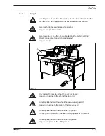
The danger and safety instructions on the machine itself are to be followed!

This machine may only be used for the purpose for which it is intended and may not be

operated without its safety devices. All safety regulations relevant to its operation are to

be adhered to.

When exchanging sewing tools (e.g. needle, presser foot and bobbin), when threading

the machine, when leaving the machine unattended and during maintenance work, the

machine is to be separated from the power supply by switching off the On/Off switch or

by removing the plug from the mains!

Everyday maintenance work is only to be carried out by appropriately trained personnel!

Repairs and special maintenance work may only be carried out by qualified service staff

or appropriately trained personnel!

Work on electrical equipment may only be carried out by appropriately trained personnel!

Work is not permitted on parts and equipment which are connected to the power supply!

Exceptions to this are only to be found in the regulations EN 50110.

Modifications and alterations to the machine may only be carried out under observance

of all the relevant safety regulations!

Содержание 3574-2/02

Страница 1: ...296 12 17 977 Betriebsanleitung engl 11 96 3574 2 02 Instruction Manual...

Страница 2: ...n whole or in part is only permitted with our previous authorization and with written reference to the source G M PFAFF Aktiengesellschaft Postfach 3020 D 67653 Kaiserslautern K nigstr 154 D 67655 Kai...

Страница 3: ...itch 7 1 7 03 Control panel 7 2 7 03 01 Display 7 2 7 03 02 Control panel operation modes 7 3 7 03 03 Functions in the SEWING mode 7 3 7 03 04 Functions in the INPUT mode 7 4 8 Mounting and commission...

Страница 4: ...program 11 20 12 Care and maintenance 12 1 12 01 Cleaning the machine 12 1 12 02 Filling the oil reservoir 12 2 12 03 Cleaning the blower air filter 12 2 12 04 Checking adjusting air compression 12 3...

Страница 5: ...13 20 13 07 Thread trimmer adjustment 13 21 13 07 01 Dismantling assembling the control unit 13 21 13 07 02 Preadjusting the control cam 13 22 13 07 03 Roller lever 13 23 13 07 04 Latch 13 24 13 07 05...

Страница 6: ...on the machine itself are to be followed This machine may only be used for the purpose for which it is intended and may not be operated without its safety devices All safety regulations relevant to it...

Страница 7: ...onnel 1 04 Important points for the user This Instruction Manual is a component part of the machine and must be available to the operating personnel at all times The Instruction Manual must be read be...

Страница 8: ...lso ensure that only authorized persons have access to the potentially dangerous area around the machine 1 05 02 Specialist personnel Specialist personnel are persons with a specialist education in th...

Страница 9: ...bjects can become trapped or be slung away Danger of injury Only operate the machine when the cover 1 is closed Danger of injury due to the action of the jig control Do not operate the machine without...

Страница 10: ...s as well as assembly and closing seams on three dimensional workpieces Any and all uses of this machine which have not been approved of by the manufacturer are considered to be inappropriate The manu...

Страница 11: ...e Length 1300 mm Width 800 mm Height without reel stand 1280 mm Sewing motor brushless DC servomotor Motor speed max 4500 rpm 1 Connection voltage 220 V 50 60 Hz Power requirement 850 VA Fuse protecti...

Страница 12: ...stics The electrical equipment consists of plastics and copper The machine must be disposed of in accordance with applicable local environmental protection regulations If necessary a specialist is to...

Страница 13: ...idual locations of use Always ensure that the machine is only transported upright 5 03 Disposal of the packaging The packaging of these machines consists of paper cardboard and VCE fiber The proper di...

Страница 14: ...n Manual tasks to be carried out and important information are drawn to your attention by symbols The symbols have the following meanings Note information Cleaning care Lubrication Servicing repairing...

Страница 15: ...7 01 On off switch By turning main switch 1 the machine is switched on or off Fig 7 02 7 02 Foot switch When the foot switch 1 is actuated the following functions are called Level 1 retain sewing jig...

Страница 16: ...ear beneath the corresponding symbols Program number from 0 99 Stitch length in mm Nominal speed in min 1 Actual speed in min 1 Quantity In the bottom line of the display various texts are shown e g i...

Страница 17: ...or continue program following interruption Seam type forwards Carry out seam type forwards step by step Combined with the program start key the seam type sequence is carried out automatically Seam typ...

Страница 18: ...via the number keys or the plus minus keys The value entered must be confirmed with the Enter key Reset unit counter The unit counter is reset to 0 Enter key For confirming input values and dialogs en...

Страница 19: ...l relevant safety regulations are to be observed 8 01 Mounting The location where the machine is set up must have a flat sturdy surface Suitable connections for supplying electricity and compressed ai...

Страница 20: ...t plug 1 in the socket and secure with the circlip Fig 8 03 Fig 8 02 8 01 03 Connecting disk drive and or programming panel For disk drive and or programming panel connect the transmission cable plug...

Страница 21: ...ses for any damage Clean the machine thoroughly and then oil machine and or fill with oil see chapter 12 Care and maintenance Have specialists ensure that the machine can be operated with the availabl...

Страница 22: ...rriage moves to home position Insert zero point jig 1 Confirm insertion of the zero point jig 1 with the plus key Feed carriage moves to current zero point To set the zero point move feed carriage via...

Страница 23: ...ork is only to be carried out by appropriately trained personnel 9 01 Inserting the needle Turn off the machine Danger of injury if machine is switched on suddenly Only use system 134 35 needles Raise...

Страница 24: ...counter clockwise around bobbin 1 a few times Switch on the bobbin winder pressing bobbin winder spindle 2 and lever 3 The bobbin fills up while you are sewing The thread tension on bobbin 1 can be a...

Страница 25: ...case Press the bobbin case 2 until you feel it engage in the bobbin 9 04 Threading the bobbin case Adjusting the bobbin thread tension Insert the bobbin into the bobbin case 1 Pass the thread through...

Страница 26: ...le thread Adjusting the needle thread tension Fig 9 05 1 2 Turn the machine off Danger of injury if machine is switched on suddenly Thread the machine as shown in Fig 9 05 Adjust the needle thread ten...

Страница 27: ...selected program station lights up Enter the number of the desired program via the number keys The program num can also be selected via the plus minus keys If the program selected is not stored in th...

Страница 28: ...program Otherwise the wrong combination of sewing jig and sewing program can cause serious damage to the machine and the sewing jig Insert workpiece in the sewing jig Insert the sewing jig in bracket...

Страница 29: ...number see chapter 9 06 Selecting the program number Call SEWING mode diode on the key must be lit Press program start key Feed carriage moves to loading position and the positioning clamp of the sewi...

Страница 30: ...enu functions are divided into three menu levels and can be called as described below also see chapter 11 01 03 Summary of the menu functions After the INPUT mode has been selected the home position i...

Страница 31: ...BOBBIN STITCH COUNTER 3 THREAD MONITOR DELAY 4 BOBBIN MONITOR DELAY 5 PRESELECT NO OF BACK ST 6 SLOW STARTING STITCHES 7 CARRIAGE START NIS 5 SWITCH FUNCTIONS 1 THREAD MONITOR FUNCTIONS 1 THREAD MONI...

Страница 32: ...with Enter Display STITCH GENERATION 213 The new stitch length value is assumed Display CHOOSE FUNCTION OR SCROLL 200 0 7 0 11 02 02 Selecting a menu function The THREAD PULLER function is to be activ...

Страница 33: ...EAD ONE PROGRAM DISC 2 READ ALL PROGRAMS DISC Depending on the subfunction selected either all of the programs or a particular program can be read from a disc into the machine memory 3 DELETE PROGRAM...

Страница 34: ...1 BOBBIN PRESELECT The number of stitches can be selected according to which the machine automatically stops for a bobbin change 2 BOBBIN STITCH COUNTER The current value of the specified stitch count...

Страница 35: ...0 and 120 5 SWITCH FUNCTIONS Under this main function the user can program machine functions according to his requirements in the subfunctions 1 THREAD MONITOR FUNCTIONS Thread monitor functions are l...

Страница 36: ...hen this function is on the carriage moves continuously during sewing When this function is off the carriage moves intermittently e g when the needle is in the material the carriage feed stops 6 TIMES...

Страница 37: ...arance under the needle must not blocked Via the plus minus keys the motor can be moved forward or backward 4 THREAD TRIMMING SEQUENCE The clearance under the needle must not blocked By pressing the E...

Страница 38: ...OGRAM NUMBER 1 601 Section number Section type Text number 11 04 01 Operation modes of the programming panel Operation modes are selected by pressing the corresponding following keys INSERT operation...

Страница 39: ...t key For confirming an error correction diode in the key is lit when there is an error message Program end End programming or correction Enter key For confirming input values and dialogs entry into f...

Страница 40: ...ons in INSERT mode Straight line When the function is active a straight line can be entered The stitch length must be defined Stitch feed motion When the function is active a single stitch can be ente...

Страница 41: ...p 2nd clamp Open close clamp Output Freely programmable outputs can be set reset Programmed stop Input of a machine stop at a particular seam pattern position without thread trimming and opening of cl...

Страница 42: ...desired type of clamp Connect programming panel to unit see chapter 8 01 03 Connecting disk drive and or programming panel Turn on main switch see chapter 7 01 On off switch Move feed carriage manual...

Страница 43: ...LINE The coordinates for the loading position are shown in the display Press Enter key 1 5 3 Enter 6 STRAIGHT LINE END POINT OF STRAIGHT LINE Turn off straight line function diode off 1 4 7 6 STRAIGH...

Страница 44: ...N mode 8 LP PROGRAM END INSERT QUICK MOTION Move to seam start of seam 1 see Fig 11 03 000 000 8 LP PROGRAM END ENTER END POINT QUICK MOTION The coordinates of the seam start are shown in the display...

Страница 45: ...12 STRAIGHT LINE STRAIGHT LINE END POINT Activate stitch feed motion 12 STRAIGHT LINE INSERT SINGULAR FEED MOTION Move to end point of seam 2 see Fig 11 03 1 0 6 1 1 5 3 Enter 12 STRAIGHT LINE ENTER...

Страница 46: ...unction 17 START SEWING Activate curve function 17 START SEWING INSERT CURVE Move to supporting points of seam 4 one after another and confirm each with the Enter key 18 CURVE POINT CURVE POINT After...

Страница 47: ...Enter key 1 5 3 Enter 29 CURVE END POINT ENTER ARC END POINT Move to arc end point see Fig 11 03 Press Enter key 1 4 0 1 4 2 1 4 3 1 4 1 30 ARC END POINT 31 TRIMMING Activate quick motion function 31...

Страница 48: ...itional supporting points must be marked Move to first supporting point see Fig 11 03 Press Enter key 1 5 3 Enter 0 0 3 2 9 2 F1 0 7 0 or 1 5 3 Enter 1 4 0 1 4 2 1 4 3 1 4 1 ENTER CIRCLE SUPPORTING PO...

Страница 49: ...ge manually to zero point right rear end position Press home position key on control panel Select the SEWING PROGRAM CORRECT function with number key 3 An existing sewing program can be carried out ei...

Страница 50: ...pattern programming Press program end key 1 7 1 1 7 0 32 QUICK MOTION CREATE STITCH DATA WITH Press plus key PROGRAMMING DISPLAY SWITCHED OFF STITCH GENERATION IN PROGRESS Press minus key if you want...

Страница 51: ...Clean air filter of filter lubricator as required These maintenance intervals are calculated for the average running time of a single shift operation If the machine is operated more often shorter int...

Страница 52: ...e 1 in oil reservoir 2 Use only oil with a viscosity of 10 0 mm2 s at 40 C and a density of 0 865 g cm3 at 15 C We recommended PFAFF sewing machine oil Part no 280 1 120 144 Fig 12 02 12 03 Cleaning t...

Страница 53: ...12 04 Fig 12 05 0 2 4 6 8 10 12 14 16 0 50 100 150 200 250 2 1 2 12 05 Cleaning the air filter of the air filter lubricator If an air compression of 6 bar is no longer achieved filter element 1 must b...

Страница 54: ...r trap Make sure knurled bush 1 is unscrewed as far as possible left thread If the water level is rising the automatic drain will open and the water drain off Place a suitable collection vessel undern...

Страница 55: ...d in the text The screws and nuts in parentheses secure those machine parts which must be loosened before adjustment and retightened after adjustment 13 02 Tools gauges and other accessories 1 set of...

Страница 56: ...p screw 5 behind the sewing head Release clamp levers 6 below the sewing head on both sides Pull the sewing head with power table 7 towards the control panel as far as it will go Unscrew star handles...

Страница 57: ...the handwheel slightly forwards and backwards until the adjustment pin engages in the crank slot behind the bearing plate and thus blocks the machine Hole 1 0 6 mm past the top dead center of the need...

Страница 58: ...oned in the TDC of the needle bar Switch on the machine Slide the feed carriage to zero point by hand see Chapter 8 04 Checking setting zero point Press the home position key on the control panel Loos...

Страница 59: ...n the BDC of the needle bar the distance between the bottom edge of needle bar 1 and the needle plate should be approx 16 5 mm Fig 13 04 Position needle bar 1 in the BDC Move needle bar 1 screw 2 with...

Страница 60: ...t BDC hole 3 1 the counter presser should be in its top point of reversal and 2 the cutout of eccentric 1 should be positioned more or less vertically below the center of the axle Position the needle...

Страница 61: ...bove the needle hole Loosen screws 1 2 and 3 behind screw 4 Move needle bar frame 5 according to the requirement Slightly tighten screw 2 Retighten screw 3 Using screw 1 pull the inner guide pin up to...

Страница 62: ...int is positioned at the center of the needle there should be a clearance of less than 0 1 mm between the hook point and the clearance cut of the needle 3 Gear wheel 5 should align with gear wheel 9 F...

Страница 63: ...st 0 5 mm between the projection of bobbin case position stop 4 and the base of the retaining groove Position the needle bar at 1 8 past BDC Turn the hook screw 1 without moving it according to requir...

Страница 64: ...ht Requirement At the left point of reversal of bobbin opener 3 the top edge of its finger should be positioned 0 5 mm above the bottom edge of trip 4 Turn bobbin opener bearing 1 screw 2 according to...

Страница 65: ...prox 0 6 mm behind the front edge of trip 5 and 2 the bobbin case base should be pushed back approx 0 3 mm from the position finger of bobbin case position stop 6 and rest against screw 4 on stop pin...

Страница 66: ...DC hole 4 bobbin opener 3 should be positioned in its right point of reversal Adjust eccentric 1 screw 2 according to the requirement To provide a better indication of the movement of the bobbin opene...

Страница 67: ...in its elongated hole that thread check spring 3 moves approx 1 mm when the thread loop is at its largest when going round the hook 4 5 2 1 2 Turn thread tension 1 screws 2 according to requirement 1...

Страница 68: ...enough thread to ensure a secure beginning of seam and without breaking the thread Adjust restrictors 1 and 2 according to the requirement The time for the thread puller can be adjusted via the contro...

Страница 69: ...h the winder 2 When the winder is switched off friction wheel 5 must not engage drive wheel 1 3 The bobbin winder should switch off automatically when the bobbin has been filled to approx 1 mm from th...

Страница 70: ...uld be in its top point of reversal Fig 13 15 Position the take up lever in its top position and loosen screw 1 Position the needle bar at TDC and turn eccentric 2 according to the requirement Positio...

Страница 71: ...depression time Requirement The presser foot should be depressed for as long as the needle is in the workpiece Position the needle bar at BDC Position articulated joint 1 screws 2 and 3 so that it is...

Страница 72: ...1 is raised there should be a distance of 1 mm between bush 3 and lever 4 1 5 6 4 3 Fig 13 17 Switch on the machine Make sure the foot switch is not actuated Risk of injury if the machine starts unex...

Страница 73: ...point of reversal 2 The lift of presser foot 4 should be adjusted to the fabric Fig 13 18 Screw in adjusting screw 1 screw 2 as far as possible Unscrew nut 3 as far as the circlip Using the handwheel...

Страница 74: ...plate should be appropriate to the fabric thickness Adjustment to uniform fabric thickness Turn nut 1 according to the requirement Adjustment to two different fabric thicknesses Adjust adjusting scre...

Страница 75: ...assemble the control unit position the needle bar at BDC Mount the control unit and slightly tighten screw 5 Actuate engaging lever 6 by hand so that roller lever 7 engages in control cam 8 Align the...

Страница 76: ...rement 1 and move it according to requirement 2 Tighten screw 4 Push retaining collar 7 onto control cam 6 Tighten screw 5 Connecting rod 1 and catch spring 3 remain dismantled for further adjustment...

Страница 77: ...er of roller lever 4 must be centered at the cam recess of control cam 7 Fig 13 22 Loosen screws 1 and 2 Apply a load to rock shaft 3 to the right Adjust roller lever 4 according to requirements 1 and...

Страница 78: ...should be a distance of 0 3 mm between latch 2 and the highest boss of control cam 1 By turning the handwheel position the bearing surface of control cam 1 with its largest eccentricity below latch 2...

Страница 79: ...tween engaging lever 1 and latch 2 when the engaging solenoid is actuated Position the needle bar at 1 8 past BDC Actuate engaging lever 1 by hand until latch 2 engages Press the magneto inductor into...

Страница 80: ...3 24V 4 ED 4 Fig 13 25 Position the needle bar at 1 8 past BDC Actuate engaging lever 1 by hand Push in roller lever 2 as far as the base of control cam 3 Slightly tighten screw 5 Position actuating l...

Страница 81: ...he thread trimmer in the resting position there should be a distance of 0 3 to 0 5 mm between the roller of roller lever 3 and the outer diameter of control curve 4 Turn screw 1 nut 2 according to the...

Страница 82: ...1 and remove knife 2 Position the needle bar at BDC Loosen screws 3 and set aside catcher stop 4 Loosen screws 5 By moving the thread catcher base position the tip of thread catcher 6 in front of the...

Страница 83: ...case position stop 4 Press the heads of connecting rod 1 onto the ball pins on the trimmer unit and on the control unit Loosen nuts 2 right and left threads Position the needle bar at BDC Actuate the...

Страница 84: ...e tip of thread catcher 6 and the center of the projection 24V 4 ED 4 4 3 5 Fig 13 29 6 2 1 2 mm 2 mm Position the needle bar at BDC Actuate the engaging lever by hand Turn the handwheel until there i...

Страница 85: ...osition there should be a distance of 0 5 mm between catch spring 1 and roller lever 3 24V 4 ED 3 2 1 0 5 mm Fig 13 30 Mount catch spring 1 together with the cover disk Slightly tighten screws 2 Push...

Страница 86: ...e 1 under the locking tab and align according to the requirement Slightly tighten screw 2 Actuate the engaging lever by hand Turn the handwheel until the wedge point in the thread catcher is just in f...

Страница 87: ...t point of reversal Take two threads double and hang them in the cutout of thread catcher 1 Continue turning the handwheel and allow the cutting operation to finish If the two threads are not cut acco...

Страница 88: ...irement 1 Allow the presser foot to rest on the needle plate Pull out the thread between the tension disks Pull down pull rod 3 screw 4 as far as it will go Position the needle bar at BDC and actuate...

Страница 89: ...Notes...

Страница 90: ...t Postfach 3020 D 67653 Kaiserslautern K nigstr 154 D 67655 Kaiserslautern Telefon 0631 200 0 Telefax 0631 172 02 Telex 45753 PFAFF D Gedruckt in der BRD Printed in Germany Imprim en R F A Impreso en...

Отзывы: