


Quick-Start Guide
Part No. 81-9059-0647-0 Rev. B
6
Step
I
NITIAL
P
OWER
U
P
I
NTEGRITY
CS S
ERIES
A2HD516 P
ROCESSOR
Inspect all connections to the processor. Ensure that all cables are installed securely.
Attach power cord to rear panel main power connector and a source of power.
Move power switch to the “ON” position.
Input
Ref
Bypass
Test
Freeze
Preset
Setup
7
Step
B
ASIC
O
PERATION
C
ONTROL
P
ANEL
L
AYOUT AND
O
PERATION
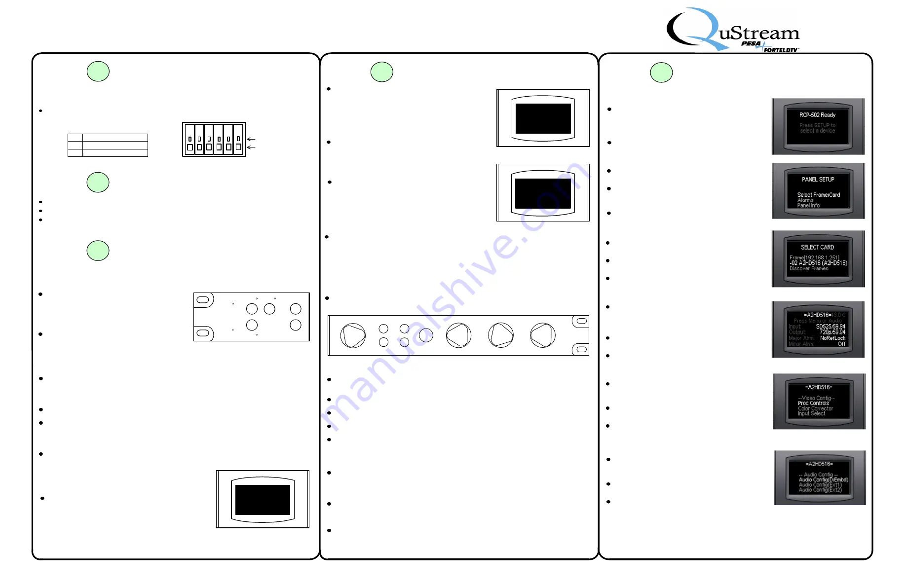
Setup
–
Setup
causes control panel to access system set-up menu regardless of
which menu screen is currently displayed.
System Status Indicators
Input
– The
Input
LED illuminates if video input signal is lost for any reason.
Reference
(Ref) – The
Ref
LED illuminates if genlock reference source is lost for any
reason.
Bypass and Preset
Bypass and Preset pushbuttons and Bypass LED are not used in current configuration
of processor.
Direct Entry Pushbuttons
Test
– Pressing
Test
switches output signal
from active video source to a user-selectable
test signal. A second pressing cancels test
output and returns to video source. The
Test
LED illuminates when test output is active.
Freeze
– Pressing
Freeze
freezes video
output signal based on a user-selectable
freeze frame type. A second pressing
cancels freeze output and returns to video
source. The
Freeze
LED illuminates when
freeze function is active.
Text Line 1
Text Line 2
Text Line 3
Text Line 4
Text Line 5
Text Line 6
Menu Display Screen
Menus, operational parameters and system status
are displayed on a six line screen, as illustrated.
=A2HD516=
--
Video Config
--
Proc Controls
Color Corrector
Input Select
Function Select Pushbuttons
Menu
– Pressing
Menu
advances to next level of menu tree structure as
determined by highlighted menu screen selection.
Back
– Pressing
Back
causes previous menu to be recalled.
Video
– Pressing
Video
accesses top level video status screen.
Audio
– Pressing
Audio
accesses top level audio configuration menu.
Take/Enter
– When
Take/Enter
pushbutton is illuminated green, it is “live” and
used in the current menu to execute a function or command. Once commands is
executed, LED in button extinguishes.
Take/Enter
performs a function only when
illuminated green.
Some menus use Function Pushbuttons to execute commands on screen. Any
button press required is prompted on individual menus.
Rotary Controls
A1 (Sel)
– The Select (
Sel
) control, also labeled
A1
, scrolls through menu entries
on scrollable screens. On data entry screens,
A1
selects commands or values for
entry mapped to it.
A2 thru A4
– On data entry screens with more than one selectable entry, control
knobs
A2 thru A4
are software mapped sequentially to data entry prompts.
7
Step
B
ASIC
O
PERATION
(C
ONT
.)
Values and parameters are modified by selecting new value or selection from a
scrolling list of available options, or increasing/decreasing numerical values, by
using rotary knobs on control panel. Data entry screens have a maximum of four
selectable values or functions, each is software mapped to one control knob,
beginning with knob A1 for first selectable entry and continuing in sequence to knob
A4 for fourth selectable entry. In this example, HUE vector may be selected by
rotating control knob A1, GAIN percentage by rotating knob A2, BLACK level by
rotating A3 and CHROMA percentage by rotating A4.
Pushbuttons and rotary controls located to right of display screen navigate menu
screens and select or modify parameters.
Hue
Sel
A1
Menu
Video
Back
Audio
Take/Enter
Gain
A2
Black
A3
Chroma
A4
S
YSTEM
I
NITIALIZATION
On power-up, a system initialization boot-
up procedure commences. Upon
completion of initialization, the screen
message shown here is displayed.
Press SETUP to advance to next screen.
7
Step
B
ASIC
O
PERATION
(C
ONT
.)
S
ELECT
C
ARD
S
CREEN
This screen allows selection of frame or device
to control.
Use
SEL
knob to highlight
A2HD516
menu entry,
as shown to right.
Press
MENU
to advance to next screen.
A2HD516 T
OP
L
EVEL
M
ENU
S
CREEN
Top level screen displays status of input and
output signals and major/minor alarm status, as
shown. From this screen you can branch to main
video and audio operation menus.
Press
MENU
or
VIDEO
to select main video
menu screen.
Press
AUDIO
to select main audio menu screen.
A2HD516 V
IDEO
- T
OP
L
EVEL
M
ENU
S
CREEN
Video configuration menus and sub-menus are
accessed through the Video Config screen, as
shown to right.
Use
SEL
knob to highlight desired menu entry, as
shown.
Press
MENU
to select desired configuration
menu screen.
A2HD516 A
UDIO
- T
OP
L
EVEL
M
ENU
S
CREEN
Audio configuration menus and sub-menus are
accessed through the Audio Config screen, as
shown to right.
Use
SEL
knob to highlight desired menu entry,
as shown.
Press
MENU
to select desired configuration
menu screen.
=A2HD516=
Video Out Proc Controls
HUE
GAIN
BLACK
CHROMA
0.0 deg
100.0 %
0 mV
100.0 %
Menus are arranged in a tree structure, and in
many instances, selecting an item brings up a
branch menu with additional entries. Often a
menu page has more items than can be shown on
the display lines. To navigate these menus, use
selector (
SEL
) knob to right of display to scroll
through entries until desired entry is highlighted.
Underscore marks before and after text identify a
text entry that describes the function of the menu
items below it. Example:
–
Video Config
–
indicates scroll list under entry contains menu
selection options for video configuration function.
Data entry screens allow changes to operating
parameters or adjustments to system settings.
Integrity CS menu structure uses a highlighted
entry to indicate a selectable function modifiable
value. In the example shown here, the value of
all four entries are highlighted, and can be
changed as desired.
P
ANEL
S
ETUP
S
CREEN
Panel Setup options allow operator to check
status and change panel operating parameters.
To initiate operation of A2HD516, use
SEL
knob to highlight
Select Frame/Card
menu
entry, as shown to right.
Press
MENU
to advance to next screen.
5
Step
V
IDEO
/A
UDIO
C
ONNECTIONS
(C
ONT
.)
A
NALOG
A
UDIO
C
ONNECTORS
The illustration and chart identify pin-out
for a typical 6-pin analog audio connector.
Pin Function
+
G
-
Positive Audio Signal
Shield
Negative Audio Signal
SUPPLIED MATING
AUDIO CONNECTOR
+ G - + G -
WIRE RELEASE
WIRE SLOT


