© Pertronic Industries Ltd
15
FAAST LT Loop-Based Installation & Maintenance Guide Iss 1.0, 201701
Intelligent Loop:
To configure the device, set the advanced parameters in the
Advanced
tab.
a) Select
Configuration
on the left pane.
b) Click the device. By default, the
General
tab appears
c) Select
Advanced
. The
Advanced Parameters
dialog box appears
In the
Intelligent Loop
tab, specify the following details:
d) Click
Apply
to implement the changes
e) Click
OK
. The main page appears.
Note:
Click
Cancel
to return to the main page without implementing changes
Detector Sensitivity:
Detector Sensitivity for Loop-Based FAAST LT detectors is configured on the
Pertronic F100
or
F120
panel
:
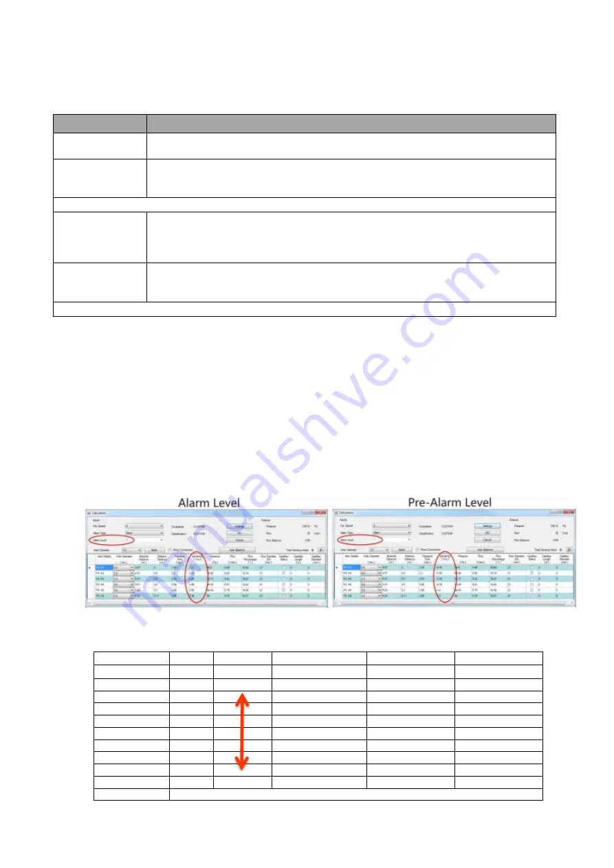
a) Configure the FAAST LT detector as Type=LASER in the F100 or F120 Config Utility to set the Alarm level
b) Define the Flags as appropriate for an ALARM within the Config
c) Configure a second address as Type=VIRTUAL (vLASER) in the F100 or F120 Config Utility to set the Pre-
Alarm level
d) Define the Flags as appropriate for an ALERT or PRE-ALARM within the Config
e) The Alarm and Pre-Alarm Sensitivity Levels are determined after the pipe network Design has been
completed and the system is correctly balanced for Flow and Transport Time.
- determine the Sensitivity required at each Sampling Point, then use the appropriate Alarm Level as
assigned during the PipeIQ Design Calculation
f) Generally, the FAAST LT ALARM level will be 3, 4 or 5. The PRE-ALARM level may be selected from 1 to
a setting less than the ALARM level selected
g) Use the following Table to determine the appropriate Sensitivity setting to use on an
F100
or
F120
panel
h) Configure the Module addresses as Type=RLYM (or AUXM if using AUX ISOLATE to isolate)
Fields
Description
Remote Output
Alarm Time:
Specify the Alarm Time for the remote output
Sensor
Communication
Timeout:
Specify the Timeout period (in seconds). The device gives a sensor communication
fault when the sensor is inactive for this period of time
Alarm Mode:
By Sensor:
In Sensor Mode, the device monitors the remote outputs.
- when the remote output is ON for the configured time, the corresponding channel
goes into Alarm.
- when the output returns to OFF, the channel exits Alarm
By Module:
In Module mode, sending an OUTPUT ACTIVATION command to a channel module
enables the channel to go into Alarm.
To exit the Alarm, an OUTPUT DEACTIVATION command must be sent
Note
When the
Alarm Mode
is
By Module
, the Alarm is not latched
Type
Sensitivity PipeIQ Sensitivity
F100
F120
Version
v5.22 or Greater
v4.24 or Greater
Pre-Alarm (Alert) vLASER
Increasing
1
1
+3
2
2
+2
3
3
+1
Alarm
LASER
4
4
0
5
5
-1
6
6
-2
7
7
-3
8
8
-4
Decreasing
9
9
-5
Limitations
2 x Alarm Levels available : Base (Alarm) plus 1 x Virtual (Alert) level


