1/01 E Service Instructions
11
Machine Size 92 (Fig. 8)
The clamp is guided by pre-
tensioned roller guideways, i. e. it
is play-free. Therefore, readjust-
ing is not necessary.
If any wear is found due to long
and hard use of the machine, the
roller guides should be replaced.
For this purpose, proceed as fol-
lows:
• Support clamp 1 by wooden
wedges, for example.
• Pull out pins 5 and slacken
screws 6 of knife beam guide strip
7.
• Remove roller guideway 4 by
slackening screws 8. Observe
the assignment of shims 3.
• Slightly tighten the new roller
guideways with their associated
shims 3 by means of screws 8.
• Re-pin knife beam guide strip 7
and tighten with screws 6.
• Check air gap a on the roller
guideway. Gap a should be
0.5 mm when the roller guideway
is properly pre-tensioned.
• If necessary, re-tension the outer
roller guide strip by means of
screws to be introduced into the
tapped holes in knife beam guide
strip 7 until gap a is obtained.
Then, tighten the roller guideway
with screws 8.
Remove the wooden wedges and
check the clamp for free move-
ment by pressing the pedal.
Machine Sizes 115/132 (Fig. 9)
• Slacken lock nuts 5 on adjusting
screws 6.
• Slightly slacken screws 7 on
adjusting strip 8.
• Reset adjusting strip 8 against
guide blocks 9 by adjusting
screws
6
until play a between the
adjusting strip and the guide block
is < 0.05 mm.
When performing this adjustment,
ensure that guide blocks 9 rest
on the opposite side of guide strip
10. For this purpose, press the
clamp towards the knife.
• After completing the adjustment,
tighten the screws and nuts and
check the play over the entire
clamp stroke with a feeler gauge.
The lateral play (face play) should
be b = 0.1 + 0.05 mm.
For this purpose, adjust support-
ing screws 11 with screws 12
slightly slackened until play b is
obtained between guide strip 10
and guide block 9. Tighten screws
12.
Clamp Parallelism
with the Cutting
Table
In the factory, the clamp is aligned
in parallel with the cutting table
surface.
This can be checked by pre-
clamping with paper strips put
under the left and right sides of
the clamp.
If correction should be neces-
sary, proceed as follows:
Machine Sizes 76/92
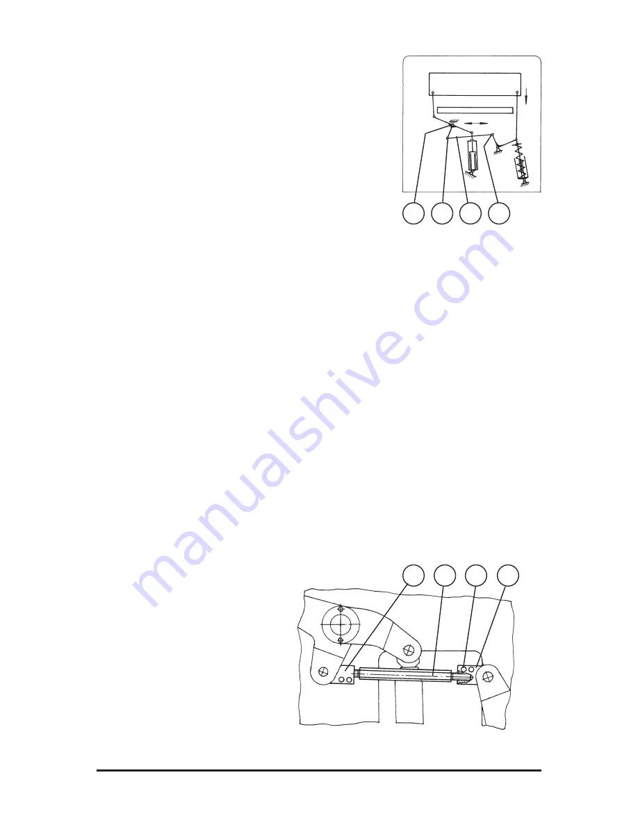
Fig. 10 shows the clamping prin-
ciple for machine sizes 76 and
92.
Machine Size 76 (Fig. 11):
• Remove the hydraulic system
front paneling under the cutting
table.
• Slacken clamping screws 1 in
pusher rod eyes 2 and 3.
• Turn pusher rod 4 as follows:
- Increasing the distance between
the pusher rod eyes moves down
the clamp on the right.
Fig. 10
Fig. 11
5
2
4
3
3
4
1
2
Содержание 115 TV
Страница 5: ...1 01 E Service Instructions 5 Fig 2 ...


