


Page 8
Mount the base to the vehicle
Select the location on the vehicle for the mount base. For the rail base, insert one screw through the two base parts and turn
on the lock nut finger tight. Hold the base up to the post or rail selected, and insert the second bolt through the base. Swing
the back plate around and over the bolt. Turn the second lock nut on finger tight. Tighten the bolts with a 3/16” hex driver
(not included).
Mount the unit to the vehicle
Hold the Phoenix by the junction of the arm and the base on the back of the unit. Lift the assembly to the base on the
vehicle. Open the arm until the end slides over the ball on that base. Tighten the wing nut firmly.
Once the Phoenix is attached, it can adjusted by holding the bottom of the Phoenix, loosening the wing nut on the arm by 1
turn moving the Phoenix to the desired position and re-tightening the wing nut on the arm.
ALWAYS hold the Phoenix before loosening the arm. Failure to hold the Phoenix can cause it to swing down
suddenly and may cause injury or damage the unit !
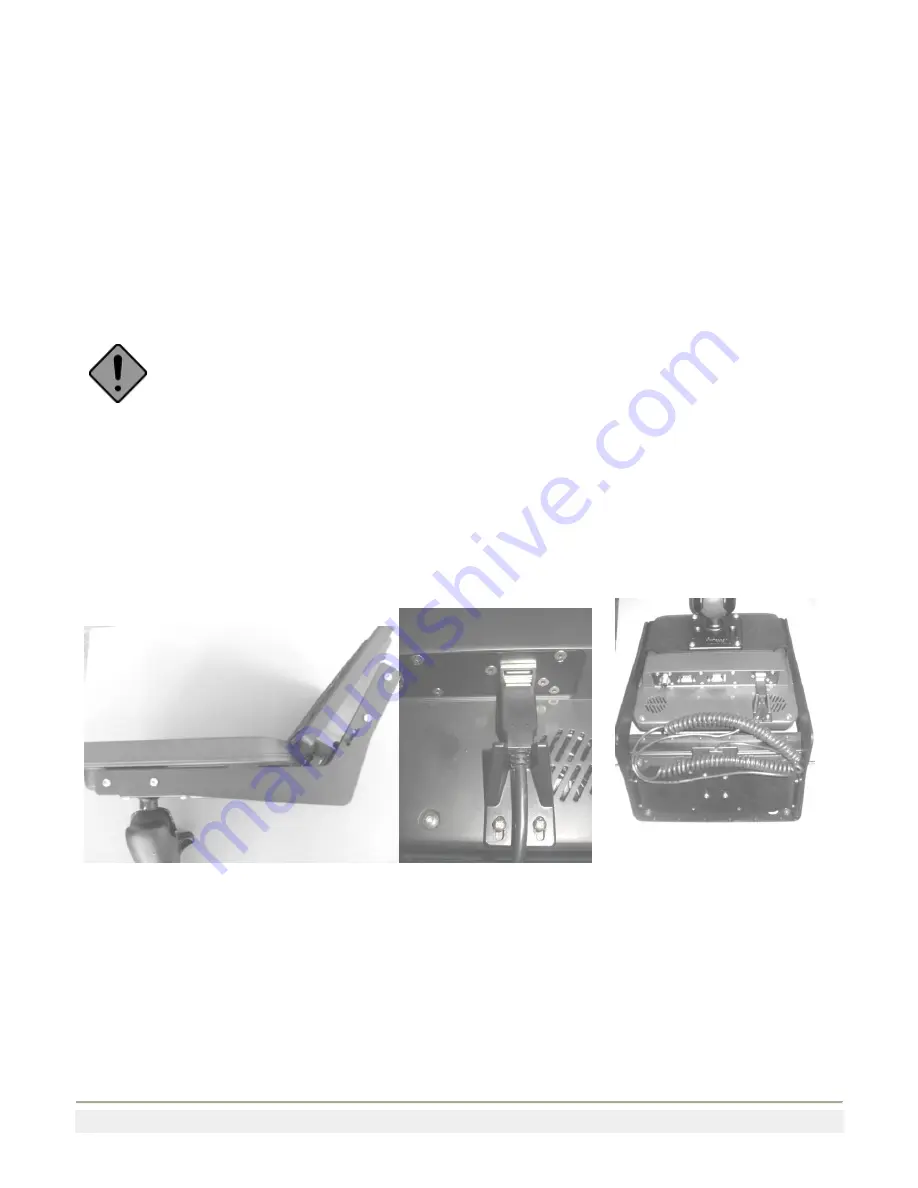
Mounting the Keyboard
Attach the long end of the two flat side supports to the flanged base on the Phoenix using four of the 8-32 screws and lock
washers provided in the keyboard mount kit. A 3/32” hex driver is required (not included). Attach the second flanged plate
to the short end of the sides with the flanges down using the four 8-32 screws and lock washers. Attach the keyboard to the
mount using the four remaining 8-32 screws and lock washers. See Figure 8.
Plug the USB cable into the top USB port on the Phoenix. Slide the USB cable into the slot in the USB cable retainer.
Position the cable retainer on the underside of the Phoenix and loosely insert the two ¼-32” screws provided. Push the
retainer firmly against the USB connector and tighten the two screws. See Figure 9.
Figure 8
Figure 9
Figure 10
Secure the keyboard cable under the keyboard mount using the 2 wire ties provided. See Figure 10.


