background image

 2

0

2

2

-0

2

54

SmartRunner Explorer

Vision Configurator Software

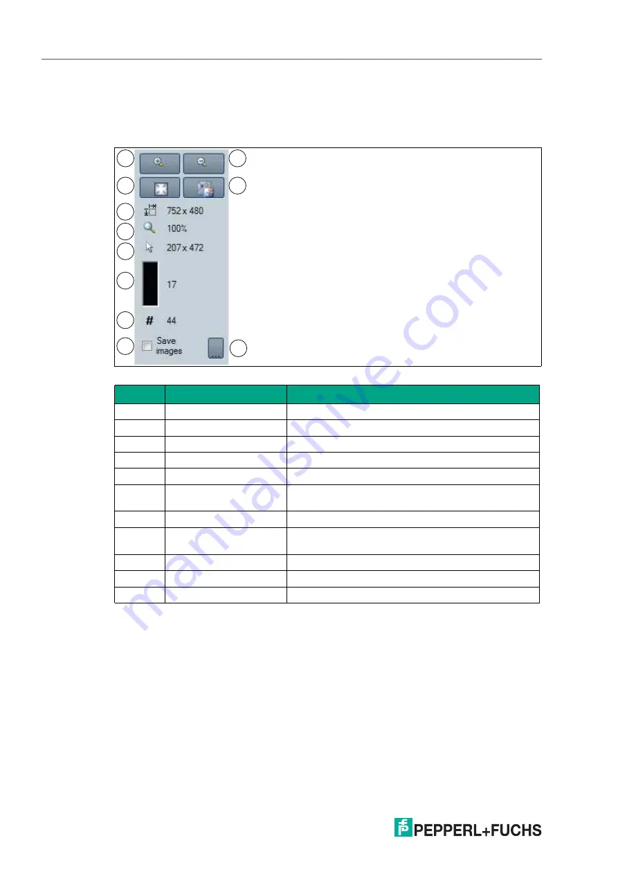
Result View - Toolbar Menu

The toolbar is located on the left side under the 

Result View

 tab. The toolbar contains several 

useful functions that are used to further process recorded images. The following functions are 
available.

Figure 6.15

Toolbar

Position

Designation

Function

1

Mag

Zoom in

2

Magnifier -

Zoom out

3

Fit to window

Fit image size to the window

4

Original size

Set original image size

5

Size details

Information field for image size

6

Zoom factor

Information field for zoom factor. A zoom factor of 100 
% is the original image size

7

Position details

Shows the position of the mouse cursor

8

Gray scale value details

Gray scale value details for the pixel indicated by the 
mouse cursor

9

Image counter

Displays the current image number

10

Save image

Saves image following transfer

11

Select path

Select path on the storage medium

1

2

3

4

5

8

7

6

9

10

11

Содержание SmartRunner Explorer

Страница 1: ...SmartRunner Explorer Light Section Sensor for High Precision Profile Capture Manual ...

Страница 2: ...rsion as well as the supplementary clause Expanded reservation of proprietorship Worldwide Pepperl Fuchs Group Lilienthalstr 200 68307 Mannheim Germany Phone 49 621 776 0 E mail info de pepperl fuchs com North American Headquarters Pepperl Fuchs Inc 1600 Enterprise Parkway Twinsburg Ohio 44087 USA Phone 1 330 425 3555 E mail sales us pepperl fuchs com Asia Headquarters Pepperl Fuchs Pte Ltd P F Bu...

Страница 3: ... 10 2 5 Interfaces and Connections 12 2 6 Network Interface 13 2 7 Software Interface 14 2 8 Accessories 15 2 8 1 Voltage Supply 15 2 8 2 Network Cable 16 3 Installation 17 3 1 Storage and Disposal 17 3 2 Preparation 17 3 3 Detection Range 18 3 4 Mounting the Sensor 18 3 5 Connecting the Sensor 20 3 6 Setting up Windows Network Communication Between the Sensor and a PC Laptop 21 4 Commissioning 24...

Страница 4: ... 3 2 View Menu 46 6 3 3 Sensor Menu 47 6 3 4 Image Menu 47 6 3 5 Administration Menu 48 6 3 6 Help Menu 48 6 4 Toolbar 48 6 5 Device Data 49 6 6 Image and Line Display 50 6 7 Configuration window 54 6 7 1 Sensor Information Tab 54 6 7 2 Common Tab 54 6 7 3 Explorer Tab 56 7 Maintenance and Repair 58 7 1 Servicing 58 7 2 Repair 58 8 Troubleshooting 59 8 1 What to Do in Case of a Fault 59 ...

Страница 5: ...cable EU type examination certificate EU declaration of conformity Attestation of conformity Certificates Control drawings Instruction manual Other documents 1 2 Target Group Personnel Responsibility for planning assembly commissioning operation maintenance and dismount ing lies with the plant operator Only appropriately trained and qualified personnel may carry out mounting installation com missi...

Страница 6: ...played in descending order as fol lows Informative Symbols Action This symbol indicates a paragraph with instructions You are prompted to perform an action or a sequence of actions Danger This symbol indicates an imminent danger Non observance will result in personal injury or death Warning This symbol indicates a possible fault or danger Non observance may cause personal injury or serious propert...

Страница 7: ...sed to project a laser line onto an object as part of the light section method This is detected by a camera at a specific angle A height profile is determined using the triangulation principle This can be output via the Ethernet TCP IP interface and conve niently integrated into the relevant program via the programming interface supplied SmartRunner Explorer consequently allows the flexible implem...

Страница 8: ...ice No 50 dated June 24 2007 The warning label is fixed to the back of the housing as shown in the following figure Figure 2 2 Laser radiation warning message Warning Class 1 laser light The laser light can be an irritant especially in a dark environment Do not point lasers at peo ple Never look into the laser beam port if the sensor is operating Maintenance and repairs must be carried out by auth...

Страница 9: ...ct Specifications 2022 02 9 2 3 Dimensions The devices in the SmartRunner series have the following identical housing dimensions Figure 2 3 Dimensions of the SmartRunner series 38 12 5 M4 55 85 98 1 32 48 5 15 35 8 M4 20 A A 14 ...

Страница 10: ...LEDs can be found in the table below 3 Function keys in Presentation mode Function key 1 Triggers an evaluation Function key 2 When pressed and held for less then two seconds activates the teach in process When pressed and held for longer than two seconds activates Code Card mode Function keys in Runtime mode Function key 1 No function Function key 2 When pressed and held for longer than two sec o...

Страница 11: ...en if the sensor is ready for operation green Flashing Flashes green if the sensor is in configura tion mode 2 POWER green On Lights up as soon as voltage is present 3 RESULT Reserved 4 TRIGGER yellow On Lights up yellow if the hardware trigger sig nal is activated 5 6 7 LINK green On Lights up green if the sensor is connected to the Ethernet yellow On Lights up yellow if the sensor is not con nec...

Страница 12: ...puts M12 plug A coded 8 pin 1 IN trigger 2 UB 3 nc 4 nc 5 nc 6 nc 7 GND LAN Network M12 socket D coded 4 pin 1 TX Ethernet 2 RX Ethernet 3 TX Ethernet 4 TX Ethernet 1 4 6 7 8 5 3 2 1 3 4 2 Tip The corner of the housing with the connections can be rotated To ensure simple cabling you can turn the connector plug in a different direction depending on the assembly position Figure 2 6 M12 connector plu...

Страница 13: ...s data transfer from the sensor to the network host XML embedded strings are used to transfer parameters and status requests The transfer of data scans images and firmware occurs as binary data The data is communicated over TCP IP via port 50005 The factory default IP address is 192 168 2 3 Figure 2 7 Network interface Host Computer Sensor Parameters XML based Calibration LUT Control commands star...

Страница 14: ...or object from which information can be obtained in the event of an error in the function A NET 5 0 based software interface is provided for easy integration with PC software This software interface takes the form of DLLs and handles the communication with the sensor Inte grate the DLLs into the programming environment and run the programming lines indicated Examples relate to the Visual Studio 20...

Страница 15: ...r Other lengths on request Field Attachable M12 Socket Model number V19 G 2M PUR ABG 8 pin M12 socket straight L 2 m Open cable end with stranded conductors V19 G 5M PUR ABG 8 pin M12 socket straight L 5 m Open cable end with stranded conductors V19 G 10M PUR ABG 8 pin M12 socket straight L 10 m Open cable end with stranded conductors Model number V19 G ABG PG9 8 pin M12 socket straight Screw term...

Страница 16: ...nnected to the network using an M12 plug Designation Description V45 G RJ45 network plug field attachable V1S G M12 plug 4 pin field attachable V1SD G 2M PUR ABG V45X G Cordset RJ45 network plug with M12 plug crossed 4 pin V1SD G 2M PUR ABG V45 G Cordset RJ45 network plug with M12 plug 4 pin ...

Страница 17: ...ntained within must be dis posed in compliance with the applicable laws and guidelines of the respective country 3 2 Preparation Unpacking the Device 1 Check the packaging and contents for damage In the event of damage inform the shipping company and notify the supplier 2 Check the package contents against your order and the shipping documents to ensure that all items are present and correct Shoul...

Страница 18: ...ge of the SmartRunner Matcher when planning your plant You will find more information on the detection range in the respective data sheet of the sensor 1 Field of view max X min X max min Z Z 1 Note The smallest possible resolution in the X and Z direction increases on a linear basis to the distance Z to the sensor ...

Страница 19: ...ote Mounting an optical device Do not aim the sensor at the sun Protect the sensor from direct long term exposure to sun Prevent condensation from forming by not exposing the sensor to any major fluctuations in temperature Do not expose the sensor to the effects of any aggressive chemicals Keep the lenses and reflector of the device clean Clean with a soft cloth using standard commercial glass cle...

Страница 20: ...ith M3 screws M4 threaded sleeves are designed in such a manner that M3 screws pass all the way through the housing Use 2 sufficiently long M3 screws with 2 lock nuts to mount the device in the plant Mounting on the underside of the device with M4 screws You can use the 2 threaded sleeves to mount the housing on the underside of the device The maximum screw in depth of the M4 screws is 5 mm Positi...

Страница 21: ...erference Establishing a low resistance or low impedance connection with the protective conductor or equipotential bonding circuit is an especially important factor in ensuring that these interference currents do not become a source of interference themselves Only use connection lines with braid Avoid connection lines with film shield because this would increase the line capacities The shielding i...

Страница 22: ...e socket on the side of the sensor 2 When delivered the sensor has a fixed IP address To facilitate communication within the network you must configure your network You can find the configuration data in the network configuration overview Note Documenting the Network Configuration The sensor communicates with the connected machine control system using the TCP IP protocol To ensure proper communica...

Страница 23: ...sted To do so proceed as follows Setting the IP Address The following section describes how to check the network connection settings of your Windows PC and adapt them accordingly The illustrations in this description were created using Windows 7 The description below also applies to later versions of Windows 1 Click the Windows Start button 2 Select Control Panel Network and Sharing Center 3 Now c...

Страница 24: ...ollowing IP address 8 Enter the IP address of the sensor but only the first three segments of the IP address The last segment must be different from the IP address of the sensor 9 In this example enter the following IP address and subnet mask IP address 192 168 2 27 Subnet mask 255 255 255 0 10 Click OK and click Cancel in the next dialog This completes the network configuration so that the device...

Страница 25: ...SmartRunner Explorer Installation 2022 02 25 Note Changes to the network settings of the PC laptop require advanced user rights If necessary consult with your administrator ...

Страница 26: ... 1 Set the operating distance see chapter 3 3 2 Mount the sensor see chapter 3 4 3 Connect the sensor see chapter 3 5 4 Set up Windows network communication between the sensor and a PC laptop see chap ter 3 6 5 Configure the sensor using the Vision Configurator configuration software see chapter 6 ...

Страница 27: ...larity this manual only describes the most important functions and variables The DLL contains additional functions that are used for other Pepperl Fuchs vision sensors These functions are described in the corresponding product manual There are several declaration options for some functions In the following the preferred functions are marked in bold Synchronous and Asynchronous Functions The auxili...

Страница 28: ...string pluginName Possible error IDs None Establish a Connection Establishes a connection to the device using the parameters set using Init CONNECTION_ TIMEOUT_MS 1000 can be used as the timeout for opening the connection A connection to the device must be established to use all non static functions Asynchronous Function public async Task bool Succ Error ErrorDesc Connect int timeout CONNECTION_TI...

Страница 29: ...Return the Value of a Single Device Parameter Returns the value of an individual parameter of the device Asynchronous Function public async Task bool Succ object parameterValue Error Error Desc GetSingleParameterValue Parameter parameter public async Task bool Succ object parameterValue Error Error Desc GetSingleParameterValue string parameterId public async Task bool Succ object parameterValue Er...

Страница 30: ...meter parameter object value public async Task bool Succ Error ErrorDesc SetSingleParameter Value string parameterId object value public async Task bool Succ Error ErrorDesc SetSingleParameter Value ushort settingsVersion ushort configVersion string configId string parameterId object value Synchronous Function public bool Succ Error ErrorDesc SetSingleParameterValue Parameter parameter object valu...

Страница 31: ...or IDs VSX_DRIVER_CONNECTION_ERROR Send the Firmware File Sends the firmware file to the device under the specified path and file name The current status can be read out via the FirmwareStateChannelReader while the update is in progress Asynchronous Function public async Task bool Succ Error ErrorDesc SendFirmware string fileName Synchronous Function public bool Succ Error ErrorDesc SendFirmware s...

Страница 32: ...n be reset by a restart or by LoadParameterSetOnDevice Only SaveParameterSetOnDevice permanently saves the parameters Asynchronous Function public async Task bool Succ Error ErrorDesc SaveParameterSetOnDe vice Synchronous Function public bool Succ Error ErrorDesc SaveParameterSetOnDevice Possible error IDs VSX_DRIVER_CONNECTION_ERROR Load Parameter Settings Loads the parameter settings saved via S...

Страница 33: ...ynamic Container The data can be called up with the GetDynamicContainer function For more details see the container description The bufferSize specifies how many containers can be buffered by the driver the startCondition specifies the container from which buffering should be per formed and the strategy determines what should happen if the buffer is full DROP_OLDEST indicates that the oldest conta...

Страница 34: ...e buffered by the driver The typeMask specifies which log data types should be transferred from the device and the strat egy specifies what should happen if the buffer is full _DROP_OLDEST indicates that the old est stored log message is discarded while DROP_WRITE means the latest log message received is discarded Asynchronous Function public void ResetLogMessageGrabber int bufferSize int typeMask...

Страница 35: ...ssages Specifies how many dynamic containers or log messages can be buffered by the driver public int DynamicContainerQueueSize get public int LogMessageQueueSize get Indication of Containers or Log Messages to be Discarded Specifies which containers or log messages should be discarded if the buffer is full DROP_OLDEST discards the oldest stored container or log message while DROP_WRITE discards t...

Страница 36: ...ring PhysicalAddress public int PhysicalPort public string IpAddress public string NetworkMask public string Gateway public string MacAddress public string Identifier public string FirmwareVersion public string SensorType Error Contains information about an error that has occurred public ErrorId Id public string Tag public string Message ...

Страница 37: ...X_DRIVER_TIMEOUT_ERROR VSX_DRIVER_SAVE_FILE_ERRO VSX_DRIVER_DATA_ERROR VSX_DRIVER_CONNECTION_ERROR VSX_DRIVER_INVALID_DATA_ERROR VSX_DRIVER_DEVICE_ERROR VSX_DRIVER_GENERAL_ERROR FirmwareState Contains information about the current status of a firmware update that is running public int Id public string Tag public string Message ...

Страница 38: ...X value of the device family usually positive in µm MinZ Minimum possible Z value of the device family positive in µm MaxZ Maximum possible Z value of the device family positive in µm FrameCounter Current frame counter related data has the same counter ScaleXYZ ScaleC Scaling factors for the internal calculation of the line data TagName Type Status Description Image ImageData Mono8 Optional Image ...

Страница 39: ... of points the points of the first line can be called directly via Line VsxDynamicContainerMessage IVsxMessage Contains a list of IVsxMessages which in turn contain data sent by the device The contained messages are identified in the list using a string The possible messages are device specific Example of a VsxDynamicContainerMessage see 2 Output of Line Data on page 40 public bool ContainsMessage...

Страница 40: ...idual image values are stored as bytes public ImageData2Format public int Width public int Height public int LinePitch public long FrameCounter public double CoordinateScale public double CoordinateOffset public double AxisMin public double AxisMax public double InvalidDataValue public byte ImageData public float ImageDataFloats ...

Страница 41: ...whether the feature is readable r writable w or both r w Config ID Parameter ID Parameter name Values read r write w Description Toolbar 0x640001 Trigger Laser 0 1 w Perform manual trigger 0x640002 LED trigger 0 1 w Perform LED trigger NOTE If auto trigger mode is enabled a line image is output via the LED trig ger GetImage Get Image 0 1 w Resend last image 0x6D0001 Teach 0 1 w Automatically adjus...

Страница 42: ...is box is not checked the exposure time is regulated automati cally during the teach in process 0x100001 Flash time 1 1000 0 r w Exposure time of used flash light when triggering LEDs in µs see 0x640002 0x9F0001 Object con trast 1 100 r w Contrast threshold for detecting laser line on object in default value 45 0xC90001 ROI min X 3200 3200 r w The lowest value on the x axis of the ROI in mm 0xC900...

Страница 43: ...x070001 0x070001 public static string Firmware_0xC30001 0xC30001 public static string Autotrigger_0x510001 0x510001 public static string Exposuretime_0x680001 0x680001 public static string Usemanualexposuretime_0xBE0001 0xBE0001 public static string Flashtime_0x100001 0x100001 public static string Presentationmode_0xFD0001 0xFD0001 public static string Objectcontrast_0x9F0001 0x9F0001 public stati...

Страница 44: ...sing the Programming Interface 1 Establishing the TCP IP Connection First all available devices are listed via UDP and an attempt is made to connect to the first device If no device was found via UDP an attempt is made to establish a connection via a fixed IP address in this case the default IP First discover devices via UDP and use the IP of the first device found var sensors await VsxProtocolDri...

Страница 45: ...To do this the container must first be collected as in example 2 Any line coordinate can then be accessed via the following program line In this case it is the first coordinate try to get a data container within 500 ms var dataItem await _vsxProtocolDriver GetDynamicContainer 500 dataItem Container now contains an image result line package if dataItem Succ dataItem Container null Check if there is...

Страница 46: ...an image If it contains an image it is saved to the BMP variable and the image is stored in png format in the Temp directory try to get a data container within 500 ms var dataItem await_vsxProtocolDriver GetDynamicContainer 500 Check if dataItem Container now exists if dataItem Succ dataItem Container null Check if there is an Image message contained if dataItem Container ContainsMessage Image var...

Страница 47: ...onfigurator software 3 Enter your user name and password Note The following user roles are predefined with different authorizations in the Vision Configurator User rights Description Password Default View all information Sensor configuration Create users at same or lower level A password is not required User View all information Sensor configuration Create users at same or lower level User Admin V...

Страница 48: ...sor and the PC laptop are ready for operation and that there is an Ethernet connection 2 Click on the Auto detect TCP IP only button 1 to search for connected sensors If a sensor 2 is detected it appears in the overview window Figure 6 1 Auto Detect in Vision Configurator 3 Click on the OK button The sensor 2 is shown on the home screen of all sensors found 4 Select the 2 D 3 D button 1 under the ...

Страница 49: ...ner Explorer Vision Configurator Software Figure 6 2 Home screen 5 Select the sensor SMARTRUNNER TCP IP 2 from the overview window 6 Click on the OK button The sensor is connected and appears in the application window 1 2 ...

Страница 50: ...menus in the program Provides an overview and helps with navigation 3 Sensor data screen Displays data for the connected sensor 4 Sensor output screen Shows the log display 5 Status bar Displays status information about the application 6 Configuration window Contains the sensor specific parameters that you can set 7 Toolbar Contains icon buttons as an extension to the menu 8 Check boxes Show image...

Страница 51: ...ed or stored in the error memory This field can be enabled or disabled via Show images 11 Tab Displays information about the current image and the pixel under the mouse pointer The following items are displayed Image size Zoom level Mouse position in image coordinates Current grayscale value Image number ...

Страница 52: ...eturns to the Login dialog Open job Loads a sensor configuration stored on the PC Save job Saves the current sensor configuration on the PC Quit Terminates the program Table 6 2 File Menu Show standard buttons Toggles the display of the buttons in the bar on the left on and off Show device data Hides the display of the sensor data in the top right of the screen Displayed message types Opens a sele...

Страница 53: ...ngs window allows you to set the IP address subnet mask gateway address and DHCP Make firmware update Performs firmware updates This command should be used by experienced users only Show device version Displays the device version Sync with sensor Synchronization with the sensor Adjust sensor calibra tion Adjust the sensor calibration Table 6 4 Sensor menu Note Firmware Update Once you have upgrade...

Страница 54: ...om the sensor on and off in the image Table 6 5 Image menu User administration Opens a window that shows all currently created users at the same authorization level or lower New users at the same authorization level or lower can also be created and deleted here In addition a user password can be reset to the default password for the relevant user level Change password Changes the current user s pa...

Страница 55: ...2022 02 50 SmartRunner Explorer Vision Configurator Software 6 3 6 Help Menu Figure 6 9 Help menu Info Displays information about Vision Configurator Table 6 7 Help menu ...

Страница 56: ...een the PC and the sensor is disconnected Opens a saved setting Saves the settings made Settings are read out from the sensor All settings made are saved on the sensor Reset to default settings Perform laser trigger to take a line image Perform LED trigger to take an area image NOTE With autotrigger activated a line image is output with Trigger LED not an area image Loads the current sensor image ...

Страница 57: ...sure is dependent on the brightness of the profile and the incident amount of light An exposure time that is too short leads to underexposed too dark images an exposure time that is too long to overexposed images There are various options available to you to display and correct recorded data to avoid errors during recording Result View Line Display You can open the currently recorded image includi...

Страница 58: ... context menu screen Designation Function Load image file Loads a sensor image You can select the sensor image Open image folder Opens the storage location Copy image to clipboard Copies image to the clipboard Save image Saves the displayed sensor image Note Note that the Image Transfer active see Image Menu Item on page 55 function is activated to show the area image Designation Function Load ima...

Страница 59: ...fier Zoom out 3 Fit to window Fit image size to the window 4 Original size Set original image size 5 Size details Information field for image size 6 Zoom factor Information field for zoom factor A zoom factor of 100 is the original image size 7 Position details Shows the position of the mouse cursor 8 Gray scale value details Gray scale value details for the pixel indicated by the mouse cursor 9 I...

Страница 60: ...ng context menu appears when you right click the graphic Figure 6 17 Diagram View context menu screen Designation Function Copy Copies diagram into working memory Save Image As Saves diagram to hard drive Page Setup Page setup for print function Print Print diagram Show Point Values Shows the values of the discrete line points in world coordinates mm as tooltip Un Zoom Undo the last zoom action Un...

Страница 61: ...eful functions that are used to further process the diagrams The following functions are available Figure 6 18 Diagram View Toolbar Position Designation Function 1 Grayscale value Grayscale value of the pixel 2 Show only valid points Shows all available points 3 Fit to line Entire visible line in field of view 4 Reset view Resets to the original view 1 2 3 4 ...

Страница 62: ...ariants only Depending on the parameters set some fields will be grayed out 6 7 1 Sensor Information Tab The Sensor information tab contains the Sensor information menu items The Sensor information menu item allows you to view more detailed information on the sensor Figure 6 19 Sensor Information Tab Vendor Name Manufacturer Homepage Manufacturer homepage Device Custom name User defined name Produ...

Страница 63: ...ing the manual exposure time The Use manual exposure time function must be activated to manually adjust the exposure time Increasing the value increases the exposure time and therefore the image brightness Values below 1000 µs are suitable in most cases Use manual exposure time When enabled the manually set exposure time is used If this box is not checked the exposure time is regulated automatical...

Страница 64: ...1 and 2 Presentation mode and function keys 1 and 2 are activated if checked and deacti vated if unchecked Figure 6 23 Mode menu item Designation Function Autotrigger Checking the box activates a cyclically recurring trigger The autotrigger must be activated in Presentation mode NOTE With autotrigger activated a line image is output with Trigger LED not an area image Designation Function Presentat...

Страница 65: ...cognized Figure 6 24 Match menu Item Teach Menu Item The Teach menu item is used to adjust the exposure time The required Teach ROI teach in range is adjusted using the line profile under the Diagram View tab The coordinates of the x and z axis are shown in the display field below the graphic Figure 6 25 Teach Menu Item Designation Function Object contrast Contrast threshold used to detect the las...

Страница 66: ...r paper cloth moistened not soaked with water or isopropyl alcohol Remove any residual alcohol using a cotton or paper cloth moistened not soaked with distilled water Wipe the device surfaces dry using a lint free cloth 7 2 Repair The device must not be repaired changed or manipulated In case of failure always replace the device with an original device Danger Danger to life due to electrical curre...

Страница 67: ...on nected Connect the connection cable Incorrect connection cable used Use the appropriate connection cable only Measurement object not rec ognized Reflections Avoid reflections Foreign exposure Avoid foreign exposure Exposure time control Set exposure see chapter 6 7 2 Teach in range set incorrectly Set teach in range see chapter 6 7 3 Measurement errors Surfaces with pronounced scored structure ...

Страница 68: ...Pepperl Fuchs Quality Download our latest policy here www pepperl fuchs com quality www pepperl fuchs com Pepperl Fuchs Subject to modifications Printed in Germany DOCT 7301A ...

Отзывы: