background image

 2

019-

03

66

OIT500-F113-B12-CB3

Communicating with the OIT System

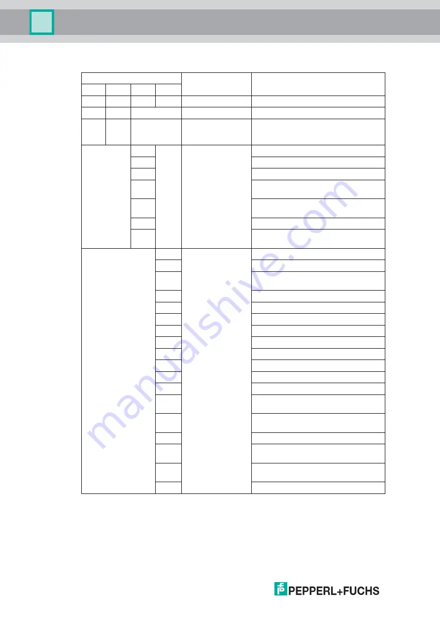
Status Table for Bytes 27

30

Byte

Group description

Subgroup description

27

28

29

30

bin

bin

bin

hex

Bit 0

Bit 5

Function could not 

be started or is not 

running

Decoder not active

Bit 0

OIT warnings

(The read-only tag 

could still be read)

Camera image too bright

Bit 1

Camera image too dark

Bit 2

Too many structures in image

Bit 3

The distance between the read-only tag 

and OIT system is too great

Bit 4

The distance between the read-only tag 

and OIT system is too small

Bit 5

Not enough contrast

Bit 6

The read-only tag is outside of the 

detection/capture range

0x01

OIT status

(The read-only tag 

could no longer be 

read)

No hole structures found

0x02

Not enough hole structures, first loop

0x03

Not enough hole structures, second 

loop

0x04

No check marks found, Check 1

0x05

Decoding not possible, Check 1

0x06

No check marks found, Check 2

0x07

Poor contrast

0x08

No check marks found, Check 3

0x0A

No check marks found, Check 4

0x0B

Decoding not possible, Check 2

0x0F

Checksum error

0x2A

Timeout

0x31

Poor read-only tag (too many possible 

hole structures)

0x32

Timeout while determining the corner 

points

0x33

Timeout while decoding

0x99

Maximum repeat read reached

Double code-reading

0x9A

Disconnection during the measuring 

process

0xFE

No usable data from the PLC

Содержание OIT500-F113-B12-CB3

Страница 1: ...OIT500 F113 B12 CB3 High Temperature Identification System FACTORY AUTOMATION MANUAL...

Страница 2: ...s of Delivery for Products and Services of the Electrical Indus try published by the Central Association of the Electrical Industry Zentralverband Elektrotechnik und Elektroindustrie ZVEI e V in its m...

Страница 3: ...1 Power Supply 11 2 6 2 Connection Cable for Trigger Sensors and External Lighting 11 2 6 3 Network Cable 12 2 6 4 Code Sheets 13 3 Mounting and Installation 15 3 1 OIT System Overview 15 3 2 Mounting...

Страница 4: ...6 Help Menu 40 5 3 Toolbar 40 5 4 Result View 42 5 5 Extended State 44 5 6 Configuration Window 47 5 6 1 System Tab 47 5 6 2 Camera Tab 49 5 6 3 Control Tab 50 5 6 4 Decoder Tab 51 5 6 5 View Tab 53...

Страница 5: ...cable EU type examination certificate EU declaration of conformity Attestation of conformity Certificates Control drawings Instruction manual Other documents 1 2 Target Group Personnel Responsibility...

Страница 6: ...instructions You are prompted to perform an action or a sequence of actions 1 4 Registered Trademarks Microsoft Windows Windows 7 are registered trademarks of Microsoft Corporation All featured tradem...

Страница 7: ...perforated matrix are used as read only tags These code sheets are designed for use at temperatures of up to 500 C and can withstand high mechanical stress The device is easy to mount and is then read...

Страница 8: ...could be read but increasing deterioration of the ambient conditions may result in a reading error This can occur for example in the following situations if the camera image is too light dark if the c...

Страница 9: ...Trigger connection 4 pin M12 socket 5 Do not use connection reserved Pinout for Power Supply Figure 2 4 Pinout for power supply 1 Do not use connection reserved 2 Do not use connection reserved 3 Do...

Страница 10: ...n Figure 2 5 Pinout for Network Connection 1 TD 2 TD 3 RD 4 Not used 5 Not used 6 RD 7 Not used 8 Not used Pinout for Trigger Connection Figure 2 6 Pinout for trigger connection 1 24 V power supply fo...

Страница 11: ...Cable for Trigger Sensors and External Lighting Use the following connection cable to connect a trigger sensor or external lighting M12 cordset Designation Description V8HAN G Field attachable female...

Страница 12: ...gled max 0 75 4 6 mm V1 G Q2 4 pin M12 socket straight 0 34 0 75 7 7 5 mm V1S G Q2 4 pin M12 plug straight 0 34 0 75 7 7 5 mm V1 G Q3 4 pin M12 socket straight 0 14 0 34 4 6 mm V1S G Q3 4 pin M12 plug...

Страница 13: ...ag with a punched hole pattern for use at high temperatures The robust code sheet is suitable for use in environments up to 500 C and remains legible even in the case of heavy contamination You can us...

Страница 14: ...chs The CB3 code sheet is still on the market but cannot be ordered from Pepperl Fuchs Note Contamination of the Code Sheet Protect the code sheet from excess dirt The code sheet can be cleaned using...

Страница 15: ...l commissioning PLC Mounting the OIT system Specifying the operating distance Setting the lighting angle Mounting and aligning the device Mounting the code sheet Establishing an electrical connection...

Страница 16: ...g injuries and significant property damage Ensure the installation is performed only by sufficiently trained and qualified personnel Trained and qualified personnel have relevant experience in this ar...

Страница 17: ...ection determines the permissible displacement of read only tags The graphic shows that as the operating distance increases the possible code sheet displacement increases The graphic is applicable pro...

Страница 18: ...eading Windows for OIC xxxx CB1 Code Sheets Code sheet displacement in the X and Y direction X Y Reading window in the X and Y direction X Y 200 150 100 50 0 50 100 150 200 Y mm Operating distance Z m...

Страница 19: ...ection determines the permissible displacement of read only tags The graphic shows that as the operating distance increases the possible code sheet displacement increases The graphic is applicable pro...

Страница 20: ...eading Window for OIC xxxx CB3 Code Sheets Code sheet displacement in the X and Y direction X Y Reading window in the X and Y direction X Y 200 150 100 50 0 50 100 150 200 Y mm Operating distance Z mm...

Страница 21: ...unit can be moved to the right position using a scale The lighting unit is preset for the CB1 code sheet as the factory default Setting the Lighting Angle to CB3 Code Sheets 1 Disconnect the device f...

Страница 22: ...Positioning on the rail CB3 4 Move the lighting unit along the rail to the CB3 position 5 Tighten the two hexagon socket cap head screws to a torque of 1 5 Nm 6 Screw the enclosure cover back down Se...

Страница 23: ...of the OIT500 system Mounting and Aligning the Device 1 Mount the device to enable easy access to the sensor connections for configuration with the associated operating software 2 Roughly position the...

Страница 24: ...ting and Installation Example In this image the contrast between the holes and the metal is too low If the tilt angle is too high the light can be reflected through some holes meaning the perforated m...

Страница 25: ...de of the housing You can use Pepperl Fuchs E2 A2 sensors with electrical outputs Creating a Network Connection For the initial commissioning of the device connect the device directly to the PC laptop...

Страница 26: ...top as described in the next chapter Note Network Connection with Degree of Protection IP65 The network connection on the OIT has degree of protection IP65 To ensure the IP65 degree of protection only...

Страница 27: ...You can use this function to display all connected Ethernet TCP IP devices You can select the device you are looking for in the output window and read information such as the device s IP address This...

Страница 28: ...settings of your Windows PC and adapt them accordingly The illustrations in this description were created using Windows 7 The description also applies to later versions of Windows 1 Click the Windows...

Страница 29: ...he input function Use the following IP address 8 Use the device s IP address that you found using the Auto detect function In this example enter the following IP address and subnet mask IP address 172...

Страница 30: ...d Note Changes to the network settings of the PC laptop require advanced user rights If necessary consult with your administrator Note Documenting the network configuration The OIT communicates via th...

Страница 31: ...5 Connecting the OIT System with Vision Configurator Establishing a Connection 1 Start the Vision Configurator software 2 Enter your user name and password 3 Double click on the device type OIT 1 Figu...

Страница 32: ...17 Connecting The connection to the device is established and the application screen opens 1 2 Note In some cases the IP address of the device may not be applied automatically In this case you must en...

Страница 33: ...evice if the sensor has transferred two images in the case of a fault Camera ExposureTime 10 20 000 default 1500 Exposure time in s Gain 0 255 default 0 Image gain StartLive 1 Starts continuous image...

Страница 34: ...second image compared to the first image SuppressDuplicates 0 1 Activate deactivate suppression of the decoding of consecutive identical codes GoodString XML string Specify which data string should b...

Страница 35: ...h different authorizations are preset in Vision Configurator User Rights and Password User rights Description Password Default View all information Create users at same level or below No password requ...

Страница 36: ...s messages relating to the captured image 3 The Device data area displays information about the connected sensor 4 The Device output area displays various items of status information such as whether a...

Страница 37: ...the Login dialog Open job Loads a sensor configuration stored on the PC Save job Saves the current sensor configuration on the PC Quit Terminates the program Table 5 1 File Menu Show standard buttons...

Страница 38: ...ow allows you to set the IP address subnet mask gateway address and DHCP Make firmware update Performs firmware updates This command should be used by experienced users only Show device version Displa...

Страница 39: ...nsor on and off in the image Table 5 4 Image menu User administration Opens a window that shows all currently created users at the same authorization level or lower New users at the same authorization...

Страница 40: ...Vision Configurator and OIT Opens locally saved settings Saves settings locally Reads the current settings from the OIT Saves the current settings to the OIT Triggers an image capture Sends the last...

Страница 41: ...OIT500 F113 B12 CB3 Commissioning 2019 03 41 Sends the last image for image A to Vision Configurator Sends the last image for image B to Vision Configurator...

Страница 42: ...Image display left and result display right Clicking the right mouse button or the context menu button calls up the following context menu Figure 5 10 Context menu in the image display Context Menu Lo...

Страница 43: ...ys the image in its original size Size details Shows the length and width of the image Zoom factor Shows the zoom factor Position details Shows the cursor position Gray scale value details Gray scale...

Страница 44: ...splayed in the upper section of the window and the status is displayed in the lower section To enable subsequent evaluation of the warning and status messages image captures must be set to single imag...

Страница 45: ...t Set the right exposure time see chapter 5 6 2 Camera image too dark The camera image is too dark Set the right exposure time see chapter 5 6 2 Too many structures in image Too many shapes in the cap...

Страница 46: ...heck 1 0x06 No corner marks found check 2 0x07 Poor contrast 0x08 No corner marks found check 3 0x0A No corner marks found check 4 0x0B Decoding not possible check 2 0x0F Checksum error 0x2A Timeout 0...

Страница 47: ...some fields will be grayed out 5 6 1 System Tab Figure 5 14 System tab Interfaces menu item Network Other Figure 5 15 System tab Image menu item Interfaces Menu Item Enable TCP IP result Activates the...

Страница 48: ...or Determines which image should be transferred to Vision Configurator after a failed reading If the capture of two images for one read operation has been activated see chapter 5 6 4 only one of the t...

Страница 49: ...10 s max 20 000 s Gain Gain setting Min 0 max 255 Start Starts the live transfer to Vision Configurator Stop Stops the live transfer to Vision Configurator Check every image Activates the check for re...

Страница 50: ...p Menu Item Trigger edge Negative edge The falling edge activates a trigger Positive edge The rising edge activates a trigger Trigger release active The following function is optional When enabled a s...

Страница 51: ...the reading of CB1 code sheets Take 2 images A B Activates the capture and evaluation of two images image A image B for one read operation If no code can be read in the first image the second image is...

Страница 52: ...coder frame in which the OIT is attempting to read a perforated matrix Figure 5 19 Decoder frame in Result View CB3 plate Menu Item Decode with Setting for data bits in the CB3 code sheet Min 8 max 12...

Страница 53: ...type Setting for the perforated matrix of the CB1 code sheet 6x6 matrix 6x6 perforated matrix 6x6 matrix mirrored 6x6 perforated matrix mirrored Graphics Menu Item Show clusters Activates optical mark...

Страница 54: ...nd the MAC ID Figure 5 24 Sensor data Example The Show clusters option allows you to determine which holes in the code sheet have been detected correctly Using this information you can adjust the ligh...

Страница 55: ...displays an overview of the communication between Vision Configurator and the OIT system Figure 5 25 Device output There are two buttons in the area at the bottom Save output Saves the Sensor Output a...

Страница 56: ...pter 6 1 TCP IP communication with Easy Mode The simplest form of connection between a PLC and the OIT system The connection is made through a simplified set of commands 6 1 TCP IP Communication with...

Страница 57: ...object to access the library functions PFVsxFactoryVCCustom _vsxFactory new PFVsxFactoryVCCustom Retrieving Parameter Data Received parameter data is stored as a list in the sensor Individual items o...

Страница 58: ...off Switches log messages off Defines whether or not the sensor sends log messages If log messages are switched on a LogDataReceived event is triggered each time a log message is received from the sen...

Страница 59: ...t frameCounter Bitmap image angezeigt IList ElementResult GetResultList ushort frameCounter frameCounter Number of the image associated with the graphics Response List of overlay graphics for the spec...

Страница 60: ...ernalError event with ErrorType LOAD_FILE_ERROR is triggered string SensorName get Returns the name of the sensor float SensorVsxVersion get Returns the VSX version installed on the sensor event Param...

Страница 61: ...when graphics for the image overlay have been received The image number specifies the image with which the graphics are associated A list of all graphics can then be retrieved using the GetShapes ush...

Страница 62: ...SaveSettingsToFile ErrorType SAVE_FILE_ERROR if the parameter data could not be saved to a file When calling LoadSettingsFromFile ErrorType LOAD_FILE_ERROR if the parameter file could not be loaded W...

Страница 63: ...operations CounterBadSuppressed Number of suppressed read operations CounterWeak Number of successful read operations Table 6 1 The result data is transferred by the SensorResultDataReceived event The...

Страница 64: ...e PLC If the read only tag was not successfully read the OIT system sends a read error to the PLC The OIT system then waits for another trigger signal Figure 6 2 Easy Mode flow chart Telegram structur...

Страница 65: ...Suppress duplicate reads in Vision Configurator is checked If you send a read command via Easy Mode the response will contain a read code even if it is a duplicate read It is also counted as suppresse...

Страница 66: ...it 6 The read only tag is outside of the detection capture range 0x01 OIT status The read only tag could no longer be read No hole structures found 0x02 Not enough hole structures first loop 0x03 Not...

Страница 67: ...cessful reading 23 90 00 00 00 09 00 00 00 04 00 00 00 02 00 00 00 09 00 00 00 30 30 30 30 35 33 00 00 00 00 B3 0D 0A Trigger Telegram via Port 50100 for Software Triggering Definition x unsigned byte...

Страница 68: ...rator is not possible The IP address is configured incorrectly The factory default IP address is 172 24 55 162 Image is not displayed in Vision Configurator The transfer of image captures to Vision Co...

Страница 69: ...hs GmbH 68307 Mannheim Germany Tel 49 621 776 0 E mail info de pepperl fuchs com USA Headquarters Pepperl Fuchs Inc Twinsburg Ohio 44087 USA Tel 1 330 4253555 E mail sales us pepperl fuchs com Asia Pa...

Отзывы: