background image

84 

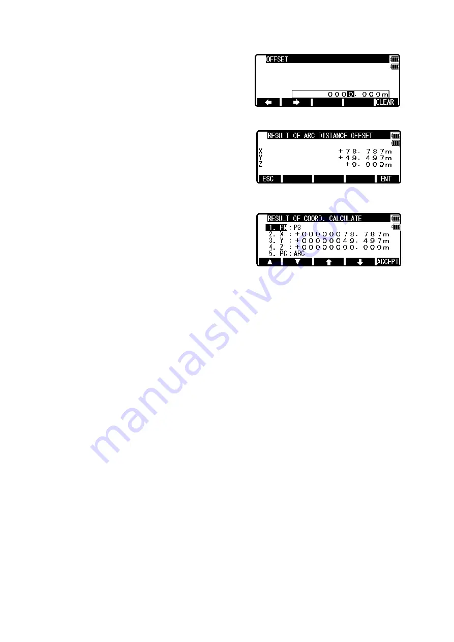
Input DISTANCE (Distance from SP to point on the 
arc).  
If you finish the input of DISTANCE, press [ENT]. 
Then you go to OFFSET input screen.  


Input OFFSET (Offset distance from the arc to offset 
point).  
If you finish the input of OFFSET, press [ENT]. 
Then you go to RESULT OF ARC DISTANCE 
OFFSET screen.  
You can see the coordinates of offset point from the 
arc.  
 
 
Press [F5][ENT] to save the coordinates of offset 
point.  


The PN, X, Y, Z and PC are viewed and can be edited.  
If all items are OK, press [F5][ACCEPT] to save them.  
 

Содержание R-2500NS Series

Страница 1: ...N R 2502N R 2503N R 2505N INSTRUCTION MANUAL Power Topo Lite TI Asahi Co Ltd International Sales Department 4 3 4 Ueno Iwatsuki Ku Saitama Si Saitama 339 0073 Japan Tel 81 48 793 0118 Fax 81 48 793 01...

Страница 2: ...lection of a Job name 15 3 3 1 Selection of a Job 15 3 3 2 Selection by a Job name input 15 3 4 Deletion of a Job name 16 3 4 1 Deletion from a Job list 16 3 4 2 Deletion from a Job name search 17 3 5...

Страница 3: ...oordinate Stake Out 47 7 2 Distance Stake Out 51 7 3 Point to Line 52 7 4 Point to Arc 55 7 4 1 Three point 56 7 4 2 Circle radius 58 7 5 Setting Out Point 60 8 CALCULATIONS 62 8 1 Cogo 62 8 1 1 Inver...

Страница 4: ...1 3 1 Writing data setting 120 13 1 3 2 Reading data setting 121 13 2 Communication with USB 122 13 3 Communication with COM 123 13 3 1 Input from the PC 123 13 3 2 Output to the PC 124 13 3 3 Communi...

Страница 5: ...tion incurred by the use of this product or malfunction of it 3 TIA shall not be liable for damage caused by usage not explained in the instruction manual 4 TIA shall not be liable for damage to this...

Страница 6: ...d highlighted choice or the displayed screen value LASER Displays the laser plummet electronic vial function and the LD point screen when you push the laser plummet electronic vial key Alphanumeric At...

Страница 7: ...the screen RETICLE F3 Changing the reticle illumination when pressing illumination key LCD F4 Changing the LCD contrast when pressing illumination key ILLU F5 Changing the LCD illumination when press...

Страница 8: ...B is switched by pressing F5 MODE ALPHANUMERIC INPUT The point name etc is input by the alphanumeric keys as following Key Letter under key Letter figure order to input 0 _ 0 1 PQRS P Q R S p q r s 1...

Страница 9: ...based on PowerTopo which is known as a versatile on board software for PENTAX ATS total station series The optimum combination of PowerTopoLite and R 2500NS hardware makes PowerTopoLite an easy and u...

Страница 10: ...s between the Memory and each Function Function Read from the stored data Write to the stored data Measure SP BSP SP BSP FP SD Stake Out SP BSP SOP SP BSP SOP OP Point to Line SP BSP KP1 KP2 SP BSP KP...

Страница 11: ...CodeList you can easily select one of the PointCode from the list or edit one of them after pressing ENT Please note that Point Code which is saved in the other job can not be referred to as a list Th...

Страница 12: ...ress the POWER ON OFF key to view the R 2500NS start up screen It turns to ELECTRONIC VIAL screen after a while R 2501NS R 2502NS only Press the ESC Laser or ENT to view MODE A screen Press the F5 MOD...

Страница 13: ...ions are viewed by pressing F5 PAGE KEY Function Description F1 TRAV Traverse F2 ROAD Road design F3 I O Input and Output F4 PREF Preference INVERSE POINT COORDINATES LINE LINE INTERSECTION functions...

Страница 14: ...ding the offset values STATION Returns to the STATION POINT SETUP screen H ANGLE Returns to the STATION POINT H ANGLE SETUP screen LIST Views the POINT SELECTION FROM THE LIST screen OTHER Views the J...

Страница 15: ...TAX are viewed on the screen The Job name PENTAX and COGOPoint are a default setting NOTE Data being used in COGO will be updated in COGOPoint file from time to time For more details refer to 8 1 COGO...

Страница 16: ...1 JOB LIST SEARCH and press ENT to view its screen JOB LIST is a list of all stored Jobs Select your desired Job name and press ENT to select 3 3 2 Selection by a Job name input Select 2 JOB NAME SEA...

Страница 17: ...his 3 4 Deletion of a Job name Select 4 DELETE by pressing the down arrow key Press ENT to view JOB DELETION screen 3 4 1 Deletion from a Job list Select 1 JOB LIST SEARCH and Press ENT to view its sc...

Страница 18: ...Press ENT to view its screen Warning When CLEAR is pushed all JobFiles are deleted NOTE Creating several new JOB files and writing in or rewriting data on the same JOB files repeatedly may cause the t...

Страница 19: ...int measurement is possible and the Remote measurement by aiming at any point is possible as well when you select the Rectangular Coordinates An operator can perform the MEASURE function only when the...

Страница 20: ...is used to scroll up down 6 PC is viewed by scrolling down 4 1 1 Point name input Select 1 PN to display the PN input screen ENT is used for both accepting the selected choice and opening the input s...

Страница 21: ...value by pressing keys Y coordinate Press ENT to view the Y coordinate input screen Input your desired Y coordinate value by pressing keys Z coordinate Press ENT to view the Z coordinate input screen...

Страница 22: ...ory Then the panel STATION POINT H ANGLE SETUP will be displayed But if STRUCTURE TYPE is selected in Action method selection it is necessary to press ACCEPT to proceed to next panel 4 1 3 Point selec...

Страница 23: ...rd Press 2 FIND PN to display PN input screen then input key word For instance if you need to search point including P1 in PN input P1 in the key word then press ENT Select the point from the list Pre...

Страница 24: ...s obtained Press ENT to finalize input Press ENT or F5 ACCEPT to view the AIM AT THE REFERENCE POINT screen Press F5 ENT to finalize BSP Press F1 ESC to redo input If you want to make measure to check...

Страница 25: ...and PC Point Code Input your desired Point name Prism height and Point code Press F5 ACCEPT if the current PN PH and PC are acceptable If PointCode exists you can easily select them from the list or e...

Страница 26: ...s key again to measure your desired point Coordinates by moving the telescope The displayed Coordinates automatically change according to your aiming point The Remote is a function of so to speak Real...

Страница 27: ...sing keys VO DO and TO values are input in the same manner After input TO value press ENT to view the MEASURE screen Or press ESC then press ACCEPT The offset values are added to X Y and Z values The...

Страница 28: ...ong the third axis DO Distance Offset Along the line of measurement thus along the slope TO Tangential offset TO On the horizontal plane perpendicular to the horizontal line between Station and Point...

Страница 29: ...ction that R 2500NS is facing Deviation represents deviation of Calculated Data If you accidentally move the instrument during the measurement the amount of error can be checked on this screen If the...

Страница 30: ...it from the list or edit one of them after pressing ENT For using Point Code List please refer to 5 4 1 Point Code If PROCESS TYPE is selected in Action method selection the input point data will be s...

Страница 31: ...ed H angle Please note that the rotation of the H angle depends on the rotation setting of Coordinate axis definition INVERS key If you want to calculate direction angle Press F5 INVERS to jump to INV...

Страница 32: ...m Height and PC Point Code Press ENT to view each input window by pressing up or down arrow key and input your desired point name or prism height or point code Press F5 ACCEPT if the current PN PH and...

Страница 33: ...OFFSET to view the OFFSET screen Offset enables you to work with Offset The following offset are available Press ENT to view the offset input window Input the RO offset value by pressing each keys DO...

Страница 34: ...n be stored at the same time in this function Press F2 MEAS of the PowerTopoLite to view the MEASURE METHOD SELECTION screen Select 3 RECT _POLAR COORD and press ENT to view the STATION POINT SETUP sc...

Страница 35: ...ult ANG DIST screen is displayed For more details refer to 14 11Meas Display Coordinates display and Angle Distance display Aim at the reference point and press ENT to view the MEASURE screen Press th...

Страница 36: ...nput the PC Point code screen If PointCode exists you can easily select them from the list or edit one of them after pressing the ENT For using Point Code List please refer to 5 4 1 Point Code Pressin...

Страница 37: ...essing F1 EDM For example change 1 PRIM MEAS KEY MEAS to TRACK SHOT or TRACK CONT if you want to use tracking measurement with PRIM MEAS KEY MEAS The target type can be selected by pressing F2 TARGET...

Страница 38: ...F2 MEAS of the PowerTopoLite to view the MEASURE METHOD SELECTION screen Select 4 IH MEASURE and press ENT to view the STATION POINT SETUP screen Press ENT to open the PN X Y and Z input window and in...

Страница 39: ...eate and edit PointCodeList For more details of PointCodeList refer to 5 4 1 Point Code 5 1 Graphical View From the PowerTopoLite screen press F3 VIEW to view its screen Press ENT to view the GRAPHICA...

Страница 40: ...to view the saved points The first line of the screen shows now displayed point and the total number of points Press F1 DELETE to delete your desired point Press F2 FIND PN to find your desired point...

Страница 41: ...to view the RECT DATA EDIT screen to edit POLAR DATA Select 4 EDIT THE POLAR DATA and press ENT to view the POLAR DATA EDIT screen Your desired points are deleted and found as described above After se...

Страница 42: ...e of Not enough data to Calculate 2 angles and 1 distance 3 angles are required appears First input the height of the IH Instrument height 6 1 Stationing by more than 3 known points 4 known points sta...

Страница 43: ...ENT or F5 ACCEPT to view the MEASURE screen Press ENT to view the ADD CALC SELECTION MENU screen Measuring is not needed Just press ENT Press the F1 ADD to view the KNOWN POINT COORD SETUP screen Aim...

Страница 44: ...ALC SELECTION MENU Press the F5 CALC to view the RESULT COORD OF STATIONING screen The Station Coordinates is displayed Result coordinates of free stationing can be saved for Station setup after press...

Страница 45: ...e Point 1 Press ENT to open the PN X Y Z PH and PC input window and input each value Then press ENT to view the MEASURE screen Press ENT to view the ADD CALC SELECTION MENU screen Press F1 ADD to view...

Страница 46: ...e RESULT COORD OF STATIONING The Station Coordinates is displayed Result coordinates of free stationing can be saved for Station setup after pressing F5 ACCEPT Horizontal angle of the result coordinat...

Страница 47: ...is extremely large See P4 and P6 on above Fig 1 3 The distance from a new point to a known point is extremely short or extremely long 4 A new point station point and three or more known points are ar...

Страница 48: ...ate Stake Out Press F1 STAK to view the STAKEOUT METHOD SELECTION screen Select 1 STAKE OUT and press ENT to view the STATION POINT SETUP screen Open the PN X Y Z IH and PC input window and input each...

Страница 49: ...ess ENT to view the STAKEOUT COORD SETUP screen Open the PN X Y Z PH and PC input window and input each Save the data by pressing F1 SAVE Press ENT or F5 ACCEPT to view the STAKEOUT screen Aim at the...

Страница 50: ...o display information with larger select ALL IN ONE INFO character select LARGE CHARACTOR Press F3 DISP to view another screen Press F3 SCROLL to view another screen Press F1 NEXT to view another scre...

Страница 51: ...he F4 NEXT to carry out staking out for the next point Press the F1 RECT M to view the MEASURE screen Refer to the 4 4 Remote Offset Station and H angle function Press the F5 PAGE to view the other ME...

Страница 52: ...ut and press ENT to View DISTANCE SELECT display It s chosen from the horizontal distance the vertical distance and during slope distance The distance of Stakeout is input The difference between the d...

Страница 53: ...he distance between the two points A and B has to be at least 1 m The two points A and B define a line and during Stake out PTL shows the deviations from the Stake out point P to the line A B At above...

Страница 54: ...pressing F2 INPUT F3 0SET and F4 HOLD or Backsight Coordinates by pressing F5 BSP Aim at the reference point and press ENT to view POINT A COORD SETUP screen Open the PN X Y Z PH and PC input window a...

Страница 55: ...sitive or negative If A Int P and A B is on the same direction Int P A is positive In case of the below drawing since A B and A Int P is on the same direction Int P A is positive Int P B Distance betw...

Страница 56: ...radius is 0 the figures of the distance between SOP and ARC is shown as a positive figure When point P is outside the circle the figures of the distance between SOP and ARC is shown as a positive fig...

Страница 57: ...and press ENT to view the STATION POINT SETUP screen Open the PN X Y Z IH and PC input window and input each Save the data by pressing F1 SAVE Press ENT to view STATION POINT H ANGLE SETUP screen Inp...

Страница 58: ...and P3 to make a circle The procedure of inputting the points is the same as that of STATION POINT SETUP After you finish with the input press F1 SAVE or F5 ACCEPT to display the measurement screen Si...

Страница 59: ...elect 1 THREE POINT and press ENT to view the STATION POINT SETUP screen Open the PN X Y Z IH and PC input window and input each Save the data by pressing F1 SAVE Press ENT to view STATION POINT H ANG...

Страница 60: ...coordinates of the center point and radius to make a circle After you finish with input press ENT to display the measurement screen Sight the target Press F1 MEAS to measure the distance From the mea...

Страница 61: ...N X Y Z IH and PC input window and input each Save the data by pressing F1 SAVE Press ENT to view STATION POINT H ANGLE SETUP screen Input the H angle by pressing F2 INPUT F3 0SET and F4 HOLD or Backs...

Страница 62: ...is measured It s chosen whether it s input whether a coordinate of Point B is measured Point B is measured Distance L and distance d are input The coordinate value of Point C Point F and Point G is c...

Страница 63: ...ection Arc Arc intersection Distance offset Point distance offset Arc distance offset 8 1 1 Inverse From the given two point Coordinates the Direction angle and distance are calculated Input Coordinat...

Страница 64: ...t 1 SP and press ENT to view SP screen LIST key All stored points can be displayed as follows by pressing F2 LIST Press F2 LIST to view POINT SELECTION FROM THE LIST screen Press ENT to open the SP in...

Страница 65: ...B End point coordinates input Input the PN Coordinates and PC of the End point After PC input EP screen is viewed Input the PN X Y Z Coordinates and PC name of the End point Press ENT to view the RESU...

Страница 66: ...65...

Страница 67: ...orizontal angle of the second point Output Coordinates of the second point From the PowerTopoLite screen press F2 CALC to view the CALCULATION screen Select 1 COGO and press ENT to view the COGO scree...

Страница 68: ...nate input screen Input your desired value by pressing keys and press ENT to go Y coordinate Press ENT to open the Y coordinate input screen In the same manner input your desired value by pressing key...

Страница 69: ...he second point Coordinates are displayed by plus or minus from the known Coordinates Press ENT to view the following screen The PN X Y Z and PC are viewed and can be edited If all items are OK press...

Страница 70: ...llowing screen The PN X Y Z and PC are viewed and can be edited If all items are OK press F5 ACCEPT to save them 8 1 2 3 H angle input In the same manner only the value of H angle is input as follows...

Страница 71: ...cle Radius The center point and radius of the circle drawn by three points are calculated by this function You can store calculated center point Input 3 points Output Center point of the arc Radius of...

Страница 72: ...press F5 ACCEPT Then you go to P2 input screen Input P2 data like input of P1 If you finish the input of P2 press F5 ACCEPT Then you go to P3 input screen If you finish the input of P3 press F5 ACCEPT...

Страница 73: ...store two possible intersection points Input Line start point and end point Arc center point and radius Output Two possible intersection points From the PowerTopoLite screen press F2 CALC to view the...

Страница 74: ...put of EP press F5 ACCEPT Then you go to CP input screen If you finish the input of CP value press F5 ACCEPT Then you go to RADIUS input screen If you finish the input of RADIUS press ENT Then you go...

Страница 75: ...d End point Second line Start point and End point Output Intersection point between the two lines From the PowerTopoLite screen press the F2 CALC to view the CALCULATION screen Press 1 COGO to view th...

Страница 76: ...e an input of S1 If you finish an input of E1 press F5 ACCEPT Then you go to S2 input screen If you finish the input of S2 value press F5 ACCEPT Then you go to E2 input screen If you finish the input...

Страница 77: ...rc 1 center point and radius Arc 2 center point and radius Output Two possible intersection points From the PowerTopoLite screen press F2 CALC to view the CALCULATION screen Select 1 COGO and press EN...

Страница 78: ...f R1 press F5 ACCEPT Then you go to C2 input screen C2 Center 2 point is center point of Arc 2 Input PN Point Name X Y Z and PC Point Code of C2 point or import from the memory of rectangular coordina...

Страница 79: ...Also new Point on the line is calculated by point of start end and offset You can store the new point Input line start point SP and end point EP offset point OP Output new point offset of new point f...

Страница 80: ...ectangular coordinate as SP by F2 LIST If you finish the input of SP value press F5 ACCEPT Then you go to EP input screen Input EP data like input of SP If you finish the input of EP press F5 ACCEPT T...

Страница 81: ...distance from start point and offset from line Input line start point and end point distance from start point DI offset from the line OD moving in the direction from start point to end point right is...

Страница 82: ...ess F5 ACCEPT Then you go to EP input screen Input EP data like input of SP If you finish the input of EP press F5 ACCEPT Then you go to DISTANCE input screen Input DI Distance from SP to point on the...

Страница 83: ...ius R distance along arc from start point DI offset from the arc OD moving in the direction from start point to end point right is positive left is negative NOTE From start point to end point must be...

Страница 84: ...Z and PC Point Code of SP point or import from the memory of rectangular coordinate as SP by F2 LIST If you finish the input of SP value press F5 ACCEPT Then you go to EP input screen Input EP data li...

Страница 85: ...Offset distance from the arc to offset point If you finish the input of OFFSET press ENT Then you go to RESULT OF ARC DISTANCE OFFSET screen You can see the coordinates of offset point from the arc Pr...

Страница 86: ...int is important If you select points by ALL or FROM TO the polygon is defined according to the order of the memory address If you select points one by one by ENT polygon is defined according to the o...

Страница 87: ...ncel the selection of the point press ENT again You can cancel the selection points one by one after pressing ALL F2 ALL key Press F2 ALL to select all stored points of current JOB The order of points...

Страница 88: ...87...

Страница 89: ...on of a polygon press F1 ACCEPT to calculate The result of calculation is displayed as follows Press ENT or ESC to return to POINT SELECTION FROM THE LIST screen You change a selection and you can cal...

Страница 90: ...ll always be convex A polygon is generated so that an area may become the biggest It is like a rope which is laid around the points and then tightens You have to give the reference height which is use...

Страница 91: ...ut reference height is between a solid In 3D Volume the case that input reference height is higher than a solid Reference Height Total Volume Positive Volume Cut Negative Volume Fill Negative Volume F...

Страница 92: ...hich compose the polygon in order at this screen If you finish point selection of a polygon press F1 ACCEPT to go to RH screen RH stands for the Reference Height Input reference height If you finish i...

Страница 93: ...e target object can be measured This makes it easy to determine the heights of electric power lines bridge suspension cables and other large items used in construction From the PowerTopoLite screen pr...

Страница 94: ...re the Point Coordinates of this virtual plane by aiming at your desired points Press the F3 VPM of the PowerTopoLite screen to view the STATION POINT SETUP screen of the VPM function LIST key All sto...

Страница 95: ...P Press ENT to open the input window when using F5 BSP Pressing F2 INPUT Input any horizontal angle Pressing F5 BSP The information for Back sight point is obtained Press ENT to finalize the input Aim...

Страница 96: ...ress F1 MEAS Measured Coordinates are displayed Press ENT to view the COORD ON THE VIRTUAL PLANE screen Aim at your desired point and press ENT The Coordinates which you aim at are displayed Pressing...

Страница 97: ...ured Any Target point can be changed to the new Reference point Press the F4 RDM of the PowerTopoLite screen to view the REF POINT screen of the RDM function 10 1 PH input Press F3 EDIT to input the P...

Страница 98: ...NT screen 10 3 Target Target distance Aim at the Target 2 and press F1 MEAS to measure a distance The distance between Reference point and Target point 2 is displayed Press F5 DISP to display the Targ...

Страница 99: ...ed each corner point s coordinates are calculated One point of the traverse data uses the memory size of two or three coordinates data Therefore please check the remaining memory The calculation type...

Страница 100: ...raverse calculation before you store other data Don t turn the power supply off until the measurement at one start point or at one corner point is completed Don t escape from the MEASURE screen You ca...

Страница 101: ...t be measured at the same time Please start the new traverse route after another traverse route is finished Press ENT to view the STATION POINT SETUP screen The mark is used to scroll up down Point n...

Страница 102: ...point s direction angle from the start point NOTE The direction angle set at this screen is used in the traverse calculation which will be executed later And the rotation of the H angle depends on the...

Страница 103: ...e Press ENT to view each input window by pressing the up or down arrow key and input your desired point name or prism height or point code Press F5 ACCEPT if the current PN PH and PC are acceptable Pr...

Страница 104: ...ss the F4 EDIT to edit the PN Point Name PH Prism Height and PC Point Code Press ENT to view each input window by pressing the up or down arrow key and input your desired point name or prism height or...

Страница 105: ...ED CALC or 4 CLOSED CALC or 5 OPEN CALC to calculate the traverse route Press ENT to view the START POINT COORD SETUP screen Start point coordinates setup Input the PN Coordinates and PC of the Start...

Страница 106: ...displayed Points being displayed Contents of e S Traverse point of Station Point The point where the instrument is set Length between last station P current P Length between start P current P Travers...

Страница 107: ...Total length is the horizontal distance error at point 1 between measured value and theoretical value Total length is the distance measured in the order of 1 2 3 4 1 For point 3 Length between last st...

Страница 108: ...erently from your desired linear shape To prevent yourself from these we recommend you to send the generated coordinates to PC and confirm the linear shape on the monitor or printer screen before usin...

Страница 109: ...ed in the right drawing can not be used which is called reverse IP or IP curve although it can be used with basic design clothoid raised type clothoid and simple curve see left drawing Terms and curve...

Страница 110: ...ed Type Input items Basic design clothoid Radius R Parameter A1 A2 Raised type clothoid Parameter A1 A2 Simple curve Radius R You can input radius R parameter A1 A2 in the range of 1m or more and less...

Страница 111: ...1 integer of number peg pitch number peg pitch is integer times of pitch curve section an error message No P isn t multiple of C P is displayed In this case input again value of number peg pitch and...

Страница 112: ...alculated based on transition curve Parabola In case of simple curve Widening is 0 at BC point the widening will be the maximum at the center of curve and widening of EC point will be 0 In case of clo...

Страница 113: ...digits NOTE If integral part exceeds 6 digits an error message TOO LARGEDATA CAL STOP is displayed and calculation is stopped NOTE Numerical part of measurement point name of number peg exceeds 999 a...

Страница 114: ...damage the instrument NOTE IP point is not stored Sample Data Point Name X Y A1 A2 R BP 110 000 120 000 IP1 180 000 140 000 50 000 50 000 80 000 IP2 220 000 280 000 50 000 50 000 80 000 EP 280 000 30...

Страница 115: ...ent as data of m unit Then it is converted according to the distance unit which is set in the instrument and displayed on the screen Data format 1 DC 1 In case of Text File read write Record No Site n...

Страница 116: ...ented by a 6 digit integer part and a 3 digit fraction part P Code The P Code is handled as text data if it is input L F code use CR LF 3 ExtCSV 31 Fixed NOTE This format is used when sending PointCod...

Страница 117: ...lar Data select 1 and in case of Polar Data select 2 then press ENT Press F5 SELECT to select format and data save place then press ENT FORMAT SELECTION Rectangular Data DC1 Extension DC1 CSV Extensio...

Страница 118: ...played Try again after increasing free memory space 13 1 2 Reading from Text File This command allows you to transfer the text file containing measurement point data in the internal memory of the inst...

Страница 119: ...ber of job files stored in the internal memory is exceeded The maximum number of job files stored in the file is 50 If you try to read a new file while 50 job files already exist an error message limi...

Страница 120: ...other Pentax Total Stations please contact us to confirm it works properly It has also been confirmed that the models mentioned in the following table can be used with the R 2500NS series Total Statio...

Страница 121: ...e axis definition They are used for matching coordinate system between definition in the instrument and definition in the external device when they are different However it is necessary to match the d...

Страница 122: ...IGHT is selected when data is transferred between the TS and PC cf 14 2 Coordinate axis definition They are used for matching coordinate system between definition in the instrument and definition in t...

Страница 123: ...direction 3 After the USB cable is removed close the SD USB slot cover completely CAUTION Be sure to open close the SD USB slot cover and insert remove the USB cable indoor Press F3 USB of the TRANSFE...

Страница 124: ...ve Hardware icon shown in the bottom right of the Desktop If you don t click this icon it may cause a loss of data In case the file that should be downloaded is not included try this procedure again B...

Страница 125: ...NFIRMATION screen Same procedure is performed for CSV format NOTE When Rect data DC1 is selected and data is transmitted to PC the DC1 format PointCode data cannot be transferred If CSV or ExtCSV is s...

Страница 126: ...ECT DATA Select the 1 RECEIVE RECT DATA and press ENT to view the following screen Press ENT to open the selection window Select each setting and press ENT Press ACCEPT when all selections are made DI...

Страница 127: ...AXIS BASIS DIRECT 10 DISP 2 AXIS RIGHT ANGLE 11 DISP 3 AXIS HEIGHT 12 ROTATION CW 13 3 3 2 Sending data setting Select the 4 COMMUNICATION SETUP and press ENT to view the COMM SETTING SELECTION 2 SEN...

Страница 128: ...600 2 DATA LENGTH 8 3 PARITY BITS NIL 4 STOP BITS 1 5 SIGNAL CONTROL ON 6 XON XOFF ON 7 PROTOCOL ON 8 RECORD DELIMETER CR LF 9 DISP 1 AXIS BASIS DIRECT 10 DISP 2 AXIS RIGHT ANGLE 11 DISP 3 AXIS HEIGHT...

Страница 129: ...ransfer with DL 01 b 1 Type of data which can be transferred With PTL POLAR DATA can be transferred by DC1 or AUX format In addition it is possible DL 01 to receive convert POLAR DATA with DC1 DC 1Z f...

Страница 130: ...A 1 BAUD RATE 1200 9600 2 DATA LENGTH 8 3 PARITY BITS NIL 4 STOP BITS 1 5 SIGNAL CONTROL OFF 6 XON XOFF OFF 7 ROTATION As you like PC DL 01 R 2500NS to RECEIVE RECT DATA 1 BAUD RATE 1200 2 DATA LENGTH...

Страница 131: ...arity None Stop bits 1 PC DL 01 R 2500 Bits per second 1200 Databits 8 Parity None Stop bits 1 c Note for the Memory capacity Data transfer failure from DL 01 to R 2500NS may cause reduction of memory...

Страница 132: ...ed on DL 01 then CSV files from PCS R 100 is selected for the type of file CSV Import Option will be appear In case the CSV data doesn t have CODE field please select PN XY or PN XYZ from following fo...

Страница 133: ...ected FIXED PLANE Compare method can be selected ALL IN ONE VIEW Aiming on off can be selected OFF EDM electronic distance meter settings can be selected PRIM MEAS KEY SEC MEAS KEY MEAS MIN DISP SHOT...

Страница 134: ...ect and press F5 ACCEPT to enter 14 2 Coordinate axis definition Select 2 COORD AXIS by pressing the down arrow key and press ENT to view the coordinate system definition window Press ENT to select an...

Страница 135: ...direction of the 1st Axis 1 BASIS DIRECTION 2 RIGHT ANGLE 3 HEIGHT 1 BASIS DIRECTION 2 RIGHT ANGLE 1 BASIS DIRECTION 1 BASIS DIRECTION 5 DISP 2 AXIS Define the direction of the 2nd Axis 1 BASIS DIREC...

Страница 136: ...of the coordinates Please note that the up arrow on the screen of the graphical view always shows BASIS DIRECTION In addition position of points doesn t change on the GRAPHICAL VIEW but value of coord...

Страница 137: ...ECT each time 3 Divided template 4 MATRIX How to input A by Matrix First press F1 R1 to view next screen Press F1 1Aa to view next screen Press F2 A to select A 14 4 Action method selection Select 4 A...

Страница 138: ...method takes over functionality of our past product When this option is selected the menu screen will be shown after inputting necessary items 14 5 Remote method selection Select 5 REMOTE METHOD and p...

Страница 139: ...emote measurement is performed on the Rotated plane which is always perpendicular to the present line of sight and induces the reference point as shown left 14 6 Compare method selection Select 6 COMP...

Страница 140: ...EST AIMING and press ENT to view the REQUEST AIMING selection window Press ENT to select and press F5 ACCEPT After pressing ENT on STATION POINT H ANGLE SETUP screen you can choose whether or not the...

Страница 141: ...tor Elevation Factor as used here refers to Average Elevation Correction and Scale Factor carried out as part of the measurement process among the special functions It is effective only with MEAS Rect...

Страница 142: ...ge Elevation Average H Averaged on site elevation Input range 9999 9998 9999 9998m 2 Scale Factor Scaling On site scaling coefficient Input range 0 00000001 1 99999998 14 10 Duplicate point check When...

Страница 143: ...TA is selected STATION POINT H ANGLE SETUP screen appears next to ANG DIST screen When RECT DATA is selected MEASURE screen is displayed 14 12 Both faces meas When ON is selected and sighting the BSP...

Страница 144: ...ave Mode If you switch to SAVE MODE you can change the display when Polar data is displayed When HA HD VD are selected at VIEW EDIT of POLAR DATA of EDIT the display will be changed as shown in the ri...

Страница 145: ...144 TI Asahi Co Ltd International Sales Department 4 3 4 Ueno Iwatsuki Ku Saitama Shi Saitama 339 0073 Japan Tel 81 48 793 0118 Fax 81 48 793 0128 E mail international tiasahi com...

Отзывы: