EQUIPMENT INSTALLATION
CONTINUED
Brine Line Connection
NOTE:
It is recommended that separate brine lines be used
for each tank.
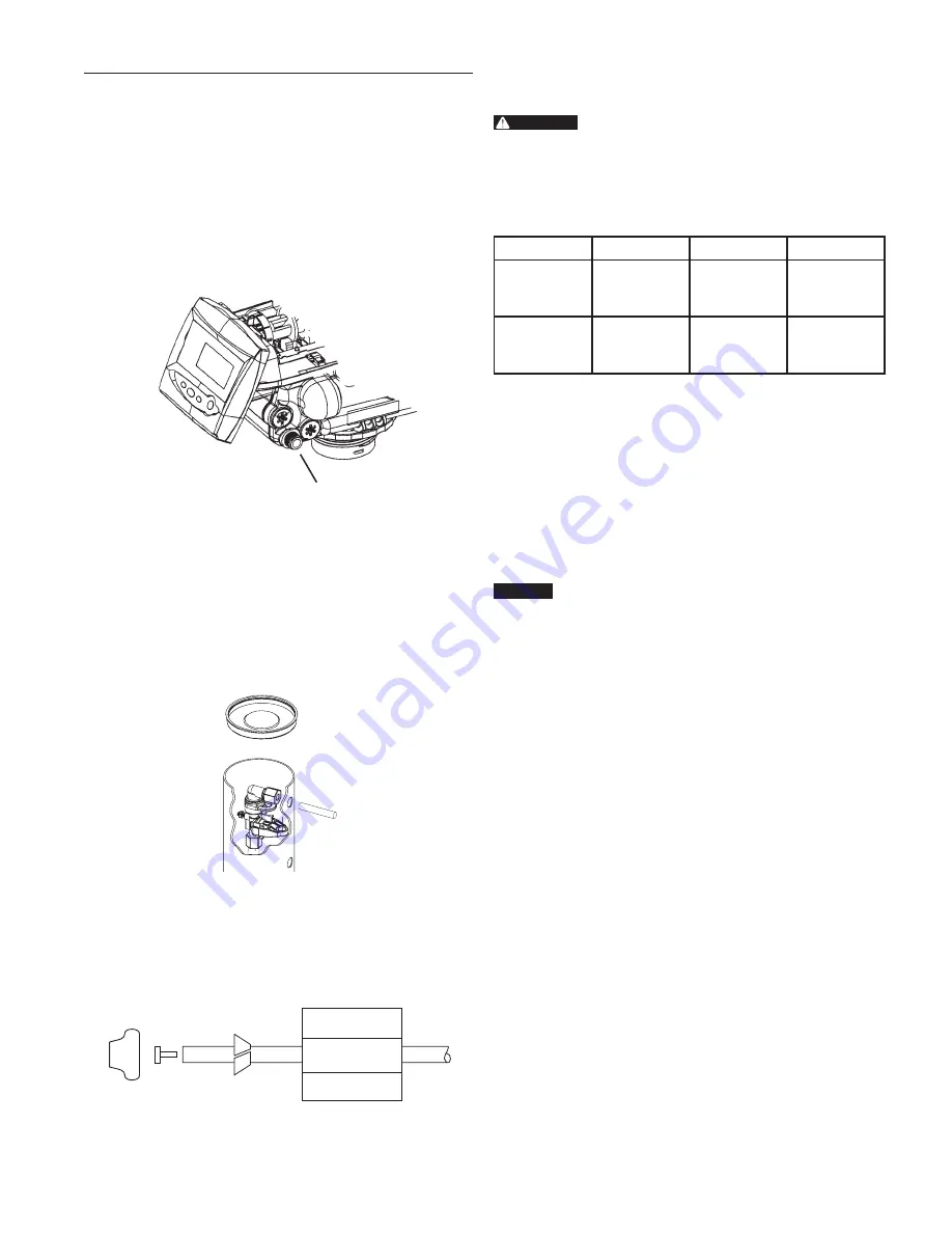
The brine line from the brine tube connects to the valve. Be
certain the connections are hand tightened. Make sure that
the salt line is secure and free from any air leaks. Even a small
leak may cause the brine line to drain out, and the system will
not draw brine from the tank. This may also introduce air into
the valve causing problems with valve operation. Ensure that
plumbers tape is applied to the 3/8" NPT brine line connection
(Figure 6 Regenerant Connection).
Regenerant Line
Connection
Figure 6 Regenerant Connection
To install the brine line:
1. Inside the brine tank, remove the cap from the large
cylinder to gain access to the connection.
2. Be sure the brass insert is in the end of the brine tubing.
Insert the tubing through the opening in the tank.
3. Push the tubing into the plastic nut. Slowly unscrew the nut
until the tubing moves into the connection. The tubing will
hit bottom.
Figure 7
NOTE:
Once the tubing has been pushed into the nut
it cannot be pulled out. The nut will need to be
removed. See Figure 8 for correct assembly.
4. Hand tighten the nut until the connection is tight.
Figure 8
Electrical Connection
WARNING:
This valve and control are for dry location use
only unless used with a Listed Class 2 power
supply suitable for outdoor use.
The 764 Series control operates on a 12 volt alternating
current power supply. This requires use of the supplied AC
adapter. A variety of AC adapters are available from your
supplier for different applications. They include:
AC Adapter
Input Voltage Application
Part Number
Standard
wall-mount
120 V 60 Hz
UL listed
for indoor
installations
1000811
Outdoor
rated
120 V 60 Hz
UL listed
for outdoor
installations
1235448
120 VAC Adapters
Make sure the power source matches the rating printed on the
AC adapter.
NOTE:
The power source should be constant. Be certain
the AC adapter is not on a switched outlet. Power
interruptions longer than eight hours may cause the
controller to lose the time setting. When power is
restored, the time setting must then be re-entered.
NOTE:
Do not connect power by plugging in the transformer
at this time. Doing so may cause difficulty in properly
placing the unit into operation.
CAUTION
Plumbing cannot be used for electrical grounding
when metal inlet and outlet piping is connected to
a non-metal valve.
Connect the inlet and outlet piping together using a
grounding strap or clamp to establish continuity.
AUTOTROL
®
Logix 764 Control Performa Cv Series Valves (273, 278) Service Manual
•
5
Содержание AUTOTROL LOGIX 764
Страница 1: ...AUTOTROL LOGIX 764 CONTROL PERFORMA CV SERIES VALVES 273 278 SERVICE MANUAL www pentairaqua com...
Страница 42: ......
Страница 43: ......


