


VENTING & AIR INLET PIPING
• Provide a minimum of 4 feet (1.22 m)
clearance distance from any door, operable
window, or gravity air intake into any building.
• Provide a minimum of 6 feet (1.83 m)
clearance to adjacent facing walls.
• Provide a minimum of 1 foot (30 cm)
clearance from the bottom of the exit terminal
above the expected snow accumulation level.
Snow removal may be required to maintain
clearance.
• Provide a minimum of 4 feet (1.22 m)
horizontal clearance from electrical meters, gas
meters, gas regulators, and relief equipment.
In no case shall the exit terminal be above or
below the aforementioned equipment unless
the 4 foot horizontal distance is maintained.
• Do not locate the exhaust exit terminal over
public walkways where condensate could drip
and create a hazard or nuisance.
• When adjacent to public walkways, locate the
exit terminal at least 7 feet above grade.
• Do not locate the exhaust termination directly
under roof overhangs to prevent icicles from
forming or recirculation of exhaust gases from
occurring.
• Provide 3 feet clearance from the inside corner
of adjacent walls.
b. Figure 3.3, 3.4 and 3.5 show approved sidewall
venting configurations using standard PVC or
CPVC fittings. A similar configuration using
FasNSeal stainless steel exhaust pipe can be used
with either PVC or other approved material for the
combustion air intake piping.
8. Figures 3.6 through 3.8 show recommended vertical
venting configurations.
a. Figure 3.6 illustrates a vertical venting
configuration using PVC inlet and exhaust. A
similar configuration can be constructed using a
FasNSeal stainless steel vent termination. PVC or
other approved materials may be used for air inlet
piping.
i. The opening of the air inlet piping is to be
a minimum of 12” (300 mm) above the
expected snow accumulation on the roof
surface.
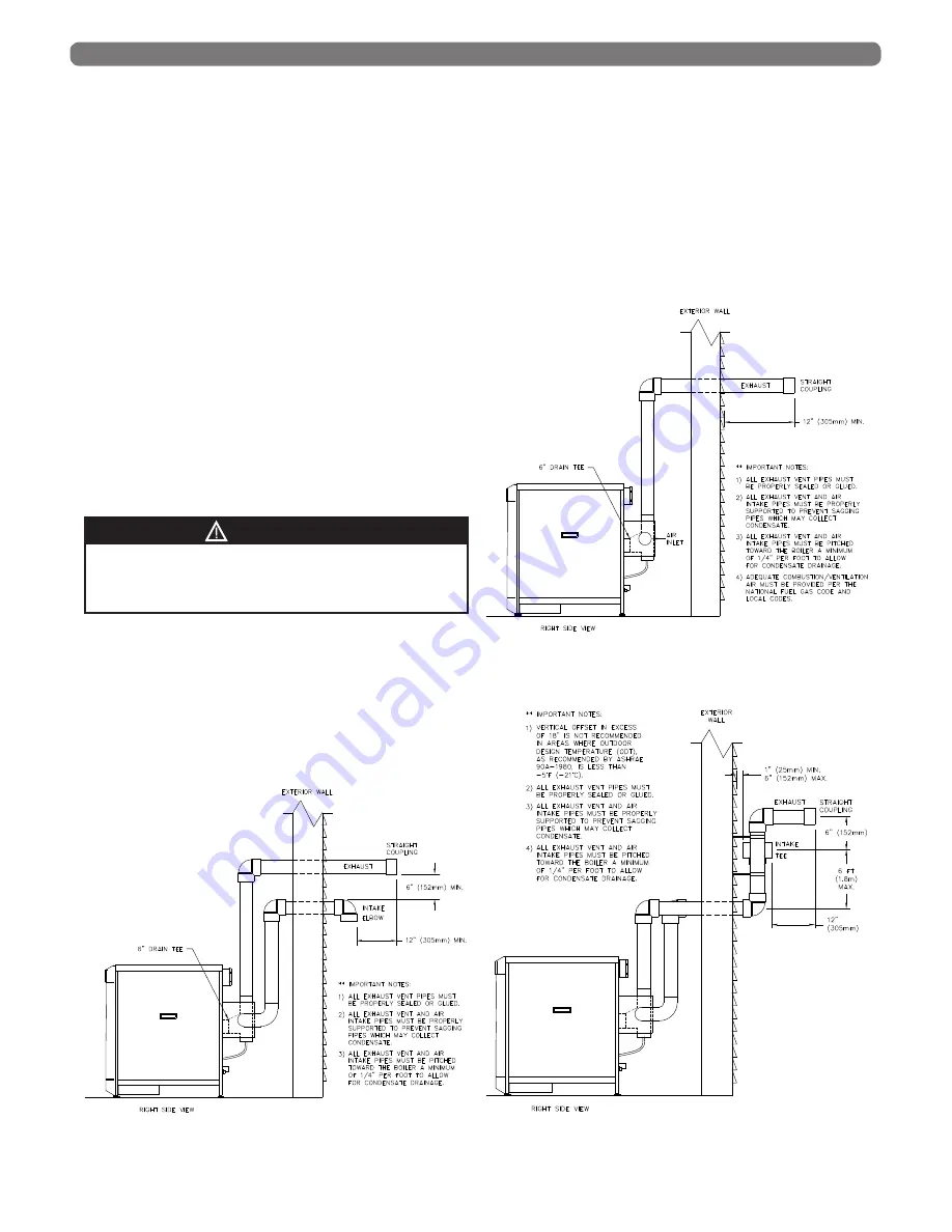
Figure 3.3: Sidewall Exhaust Vent and Air Inlet Pipe
Figure 3.4: Sidewall Exhaust Vent with Indoor Air
11
Condensing flue gases can freeze on exterior
building surfaces which may cause discoloration and
degradation of the surfaces.
CAUTION
Figure 3.5: Offset Sidewall Exhaust Vent and Air
Inlet Pipe
Содержание PureFire PFC-625
Страница 1: ...PureFire Boilers PFC 625 PFC 750 Gas Installation Operation Maintenance Manual ...
Страница 24: ...22 WATER PIPING CONTROLS Figure 4 4 Recommended Piping One Boiler with Multiple CH Zones One DHW Tank ...
Страница 25: ...23 WATER PIPING CONTROLS Figure 4 5 Recommended Piping Multiple Boilers with Multiple CH Zones One DHW Tank ...
Страница 36: ...34 ELECTRICAL CONNECTIONS INTERNAL WIRING Figure 7 4 Internal Wiring Schematic for PFC 625 PFC 750 boilers ...
Страница 58: ...56 J LIGHTING OPERATING INSTRUCTIONS Figure 9 1 Lighting Operating Instructions START UP PROCEDURE ...
Страница 76: ...74 REPAIR PARTS 2 9 8 7 2 4 2 1 3 6 6 5 2 10 5 Figure 13 3 Supply Return Piping ...
Страница 78: ...76 REPAIR PARTS 18 16 17 6 14 15 9 4 3 1 8 13 18 7 19 2 10 11 12 5 Figure 13 4 Jacket Assembly ...
Страница 82: ...80 REPAIR PARTS Figure 13 6 Condensate System 1 2 4 7 5 15 15 8 11 3 10 15 6 15 15 12 15 13 15 9 15 14 15 ...
Страница 87: ...85 SERVICE LOG SERVICE LOG Date Serviced By Description of Service Serial Number ...