9 / 14
In order to vary the level of switching on and off of the pumps and the level of activation of the alarm
system and to adapt them to your needs, adjust the length of the float cables operating the relevant
cable ties.
2.1 Input pipes
In the SAR40 pumping stations the input pipe must be connected to the tank with a 1 ½” GAS threaded
junction.
In the SAR100, SAR250 and SAR550 pumping stations the input pipe must be connected to the tank
with a PVC DN 110 junction, whose seal must be ensured with a specific glue.
Depending on the typology of installation and on the local regulations in force, it may be necessary to
include a siphon on the connection pipe to the sewers.
2.2 Output pipes
The connection pipe with the sewers must be connected to the tank with 1 ¼”, 1 ½“ or 2” GAS threaded
junctions, depending on the pipe model.
In order to facilitate maintenance operations and avoid back flows, it is advisable to use a non return
valve and a stop valve.
Depending on the typology of installation and on the local regulations in force, it may be necessary to
include a siphon on the connection pipe to the sewers.
2.3 Aeration pipe
Tank aeration must be ensured connecting the aeration port (DN50) to an outgoing aeration duct and
making sure that the mouth of such a pipe is outdoors and that the vented gases cannot penetrate
nearby buildings.
Always refer to the local and/or national regulations, laws and directives in force.
3 - MAINTENANCE
It is suggested to carry out regularly an inspection and, if necessary, to clean the non return valve and
the pump induction valve, removing any foreign body or residue that may prevent the correct operation
of the system. Also check that the floats may move freely.
It is suggested to carry out at least once a year the cleaning of the system with running water, starting
up the pump repeatedly.
4 – SAR SYSTEMS WITH 1 SINGLE-STAGE PUMP WITHOUT ELECTRIC CONTROL PANEL
(SAR40, SAR100 and SAR250 only)
The motor-driven pump is supplied with control float, integrated thermal motor guard and supply cable
with Schuko plug. Once all the hydraulic connections have been made, just plug in the station and it will
be ready for operation.
5 – SAR550 SYSTEMS
Motor-driven pumps are provided without control float and with an integrated thermal motor guard. The
station is complete with a control panel to which the floats and the motor-driven pumps must be
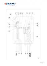
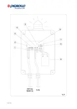
connected, following the diagram in Fig. A and the subsequent indications.
5.1 Technical features and operation of the control panel for two single-stage pumps
-
230V ± 10% - 50/60Hz single stage power supply;
-
IP55 thermoplastic material shell
-
General isolator with door block (15);
-
Control input with three floats (GMIN, G1, G2)
-
Input for motor-integrated thermal protection (2)
-
Alarm control input from N/O contact (GA)
-
Output for alarm horn on faston (12 V DC – max 30mA) (3)
-
Adjustable electronic motor protection (5)
-
Internal selector for ‘alarm’ exclusion (6)
-
Internal selectors for ‘Delay of overload protection operation’ exclusion (8, 9)
-
Selector for the activation/deactivation of pump exchange (4)
-
Selector for the activation/deactivation of the self-retention functions on floats (1)
-
‘NETWORK PRESENCE’ indicator light LED;
-
‘ALARM’ indicator light LED for min/max water level;
Содержание SAR100
Страница 2: ...2 14 INDEX ITALIANO pag 3 ENGLISH page 8 LEGENDA KEY page 13...
Страница 13: ...13 14...
Страница 14: ...14 14...


