10 / 14
-
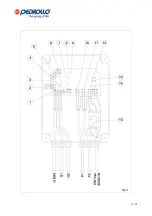
‘FUNCTIONING MOTOR’ indicator light LED;
-
‘PROTECTED MOTOR’ indicator light LED;
-
Buttons for motor ‘automatic – off – manual’ operation;
-
Motor protection fuses (13);
-
Auxiliary circuit protection fuse (14);
-
Alarm output with N/O – C – N/C exchange contacts. Delivery 16A – 250V
-
5.2 Operation of the panel with active SELF-RETENTION function
The pumps are activated by the closing of contacts G1 and G2 and they continue to work also when G1
and G2 are opened. The pumps only switch off when the GMIN contact is opened.
Closing the G1 contact activates alternately pumps P1 and P2, while closing the G2 contact activates
the second pump (P2 if P1 is already working or vice versa).
Disengaging selector (6) it is possible to exclude the LED switch on and the contact exchange on
terminal box (8) when the GMIN contact is opened. The exclusion is useful when, with selector (1)
engaged, the self-retention function is triggered and the activation of the GMIN opening alarm is
unwanted.
5.3 Operation of the panel with excluded SELF-RETENTION function
The G.MIN contact acquires a function of protection against dry operation and the pumps are activated
and deactivated through the G1 and G2 controls only if the G.MIN contact is closed.
Closing the G1 contact activates alternately pumps P1 and P2, while closing the G2 contact activates
the second pump (P2 if P1 is already working or vice versa).
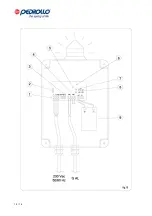
If the pumps have the 2 cables for the thermal protection of the coil, the former must be connected to
the terminal box (2); opening of the contact blocks the motor operation and switches on the related LED
on the panel board. If there is no integrated protection in the motor inputs T1 and T2 must be closed
with a bond.
6 – INSTALLATION AND ACTIVATION OF THE CONTROL PANEL FOR TWO SINGLE-STAGE PUMPS
5.
Fix the panel to a wall by means of appropriate screws and dowels, using the ports on the box;
the panel must be installed in a closed, ventilated environment, in which there are no dust,
acids, corrosive and/or inflammable gases. The room temperature must be b4°C and
+40°C.
6.
Set up the electrical connections as shown in the attached diagram, making sure that the power
supply voltage is appropriate for the panel and the motor-driven pump (230V±10% 50/60Hz).
7.
Remove any plastic or metal impurity (e.g. copper fragments from the cables, plastic slivers, dust,
etc.) inside the box and power the panel. On the front board the green ‘LIVE’ LED switches on
8.
Calibrate the overload protection pursuant to the paragraph below.
7 – CALIBRATION OF THE OVERLOAD PROTECTION TRIGGERING CURRENT
The control panel is equipped with an adjustable electronic protection which allows, when the current value is
adequately set, to obtain in all cases the ideal protection for the motor-driven pump.
In order to calibrate the protection follow the procedure below:
-
Check that selectors (8) and (9) are activated, so that the delay of amperometric protection operation
is zeroed.
-
Move the potentiometers (5) clockwise and set the maximum value;
-
Start up with the manual control pump P1 and move the related potentiometer counterclockwise until
the red ‘PROTECTED MOTOR’ LED on the front panel board switches on and the motor turns off.
-
Increase the current value so obtained by 10÷20%.
-
Start up with the manual control pump P2 and move the related potentiometer counterclockwise until
the red ’PROTECTED MOTOR’ LED on the front panel board switches on and the motor turns off.
-
Increase the current value so obtained by 10÷20%.
-
Deactivate selectors (8) and (9) if you want to set a delay time equal to around 5 seconds in the
amperometric protection operation.
Содержание SAR100
Страница 2: ...2 14 INDEX ITALIANO pag 3 ENGLISH page 8 LEGENDA KEY page 13...
Страница 13: ...13 14...
Страница 14: ...14 14...


