DRAFT
MTSE
IO&M Manual
17
Paragon Controls Inc,
Rev J 2/3/2021
Alternatively, if the user knows the percent change required to match the balancer’s reading, the K-
Factor can be entered directly by pressing the K-Factor box for that system and entering the desired
value in the popup keypad.
The K-Factor has a limit of 0.5 and 2.0. If values are required outside these limits troubleshooting
should be conducted to determine the device is configured correctly and that there are no problems with
installation, such as kinked or leaking signal tubing.
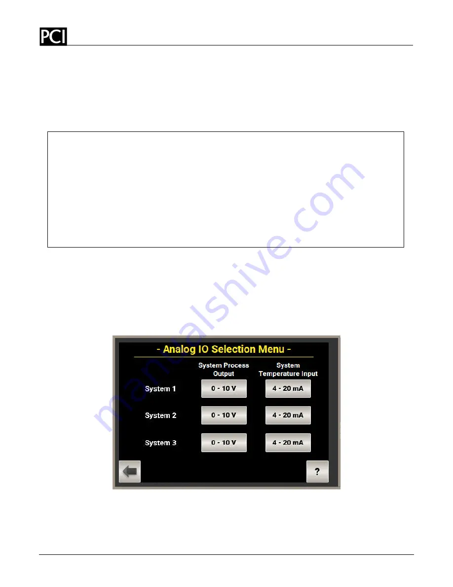
4.2.3. Analog I/O Configuration
In this menu the user can select the signal type for analog input and analog output for each system.
Selections are made through toggle buttons of available options on the touchscreen. Selections available
for the System Process Outputs are 0-10V and 4-20mA. Selections available for the System
Temperature Inputs are 0-5V, 0-10V, and 4-20mA.
Default will be 0-10V for Analog Outputs and 4-
20mA for Analog Inputs.
The Analog IO page is shown below.
4.2.4. System Filters
The System Filters menu allows the user to independently adjust the rolling average calculation by
setting the Number of Samples count and the Sampling Interval Time value in seconds for each System.
The Number of Samples count range is 1 to 99 sample counts. The adjustment range of the Sample
Interval Time is 1 to 65 seconds. The system filters effect both the display values, network
FLOW CORRECTION EXAMPLE
The balancer is consistently measuring a value of 9,500 CFM, which is 500 CFM less than the
10,000 CFM MTSE value at the time of the balancer measurement. The user would then
perform the following math function:
Balancer Measurement / MTSE Measurement = K-Factor, so
9,500 CFM / 10,000 CFM = 0.950
The user would enter 0.950 for the K-Factor Flow Correction. If the K-Factor Calculator is used
and the values entered into the boxes on this menu and the calculate button is pressed, the K-
Factor Flow Correction would automatically update the K Factor.


