Introduction
34
SmartNode 5541 & 4141 Series User Manual
4
• Initial Configuration
Introduction
This chapter leads you through the basic steps to set up a new SmartNode device and to download a
configuration.
Note
If you haven’t already installed the SmartNode device, refer to Chapter 3,
If you are installing an SN5541, see section
“Connecting the SN5541 to your laptop PC”
. Otherwise, to install
an SN4141, see section
“Connecting the SN4141 to a laptop PC”
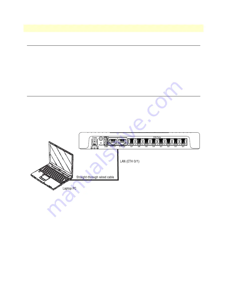
Connecting the SN5541 to your laptop PC
First, the SmartNode device must be connected to the main power supply with the power cable. Wait until the
Power LED stops blinking and stays lit constantly. Now the SmartNode device is ready.
Note
The SmartNode device is equipped with Auto-MDX Ethernet ports, so you
can use straight-through cables for host or hub/switch connections (see
Figure 11. Connecting the SmartNode device to your laptop PC
The SmartNode device comes with a built-in DHCP server to simplify configuration. Therefore, to
automatically configure the PC for IP connectivity to the SmartNode device, the laptop PC must be
configured for DHCP. The SmartNode will provide the PC with an IP address. You can check the connection
to the SmartNode by executing the ping command from the PC command window as follows:
ping 192.168.1.1
Configure the desired IP address
Factory-default IP Settings
The factory default configuration for the Ethernet interface IP addresses and network masks are listed in
.
Both Ethernet interfaces are activated upon power-up. LAN interface
ETH 0/1 (LAN)
provides a default
Содержание SmartNode 5541 Series
Страница 49: ...49 Appendix C Cabling Chapter contents Introduction 50 Ethernet 50 Analog FXS 51 ...
Страница 52: ...52 Appendix D Port pin outs Chapter contents Introduction 53 Ethernet 53 FXS port 53 ...
Страница 54: ...FXS port 54 SmartNode 5541 4141 Series User Manual D Port pin outs Figure 18 RJ 11 pinout diagram ...
Страница 55: ...55 Appendix E SmartNode Device Factory Configuration Chapter contents Introduction 56 ...


