Installing the SmartNode device
32
SmartNode 5541 & 4141 Series User Manual
3
• SmartNode Installation
2.
The power connection is made via the barrel jack on the rear panel of the SmartNode. No configuration is
necessary for the power supply.
Connect the female end (barrel plug) to the barrel jack on the rear of the SmartNode (see
on page 19 for an SN4141) and the power supply male connectors to
an appropriate power outlet.
3.
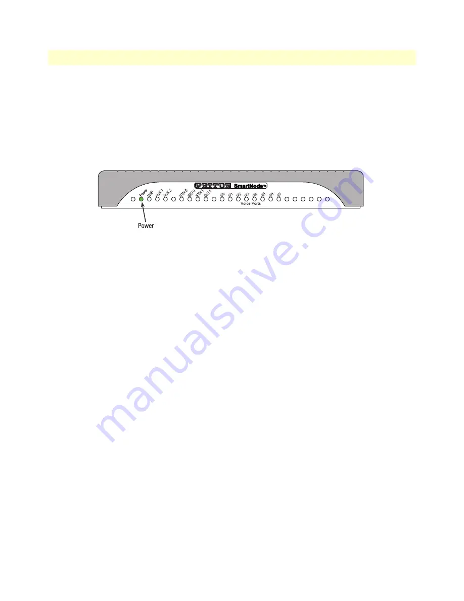
Verify that the green
Power
). It blinks fast during bootloader phase and blinks slow
during boot process of Trinity Software. It becomes solid when the system is up and running.
.
Figure 10. Power LED
Congratulations, you have finished installing the SmartNode device! Now go to Chapter 4,
Содержание SmartNode 5541 Series
Страница 49: ...49 Appendix C Cabling Chapter contents Introduction 50 Ethernet 50 Analog FXS 51 ...
Страница 52: ...52 Appendix D Port pin outs Chapter contents Introduction 53 Ethernet 53 FXS port 53 ...
Страница 54: ...FXS port 54 SmartNode 5541 4141 Series User Manual D Port pin outs Figure 18 RJ 11 pinout diagram ...
Страница 55: ...55 Appendix E SmartNode Device Factory Configuration Chapter contents Introduction 56 ...


