Installing the VoIP IAD
35
SmartNode 4830 User Manual
3 • Hardware installation
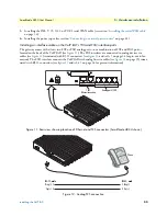
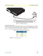
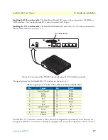
Figure 14. Analog FXO connection
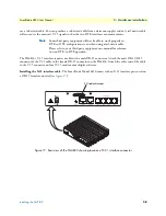
Installing the Ethernet cable
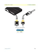
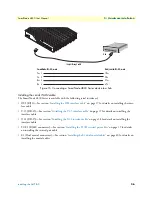
The SmartNode 4830 Series has automatic MDX (auto-cross-over) detection and configuration on the Ether-
net ports. Any of the two ports can be connected to a host or hub/switch with a straight-through wired cable
(see
figure 15
). Ethernet devices (10Base-T or 100Base-T) are connected to the SmartNode’s Ethernet port(s)
(see
table 6
for port pin-out listing) via a cable terminated with RJ-45 plugs.
Note
Pins not listed are not used.
Table 6. Ethernet 10/100Base-T (RJ-45) port pin-outs
Pin
Signal
1
TX+
2
TX-
3
RX+
6
RX-
RJ-11, male
RJ-11, male
PSTN
wall plate
Ring (-) 3
Tip (+) 4
3 Ring (-)
4 Tip (+)


