Installing the VoIP IAD
33
SmartNode 4830 User Manual
3 • Hardware installation
3.
Installing the DSL, V.35, X.21, or T1/E1 serial WAN cable (see section
“Installing the serial WAN cable”
on page 36)
4.
Installing the power input (see section
“Connecting to external power source”
on page 41)
Installing an interface cable on the VoIP IAD’s FXS and FXO interface ports
The gateway comes with at least two FXS or FXO analog ports—or a combination of FXS and FXO ports—
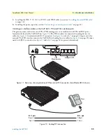
located on the back of the VoIP IAD (see
figure 11
). The FXS interfaces are connected to analog devices via
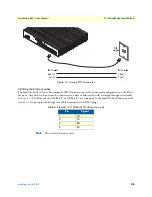
cables (see
figure 12
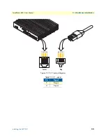
) terminated with RJ-11 connectors (see
figure 13
and
table 5
on page 34 for pin-out infor-
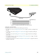
mation). The FXO interface connects the VoIP IAD with analog lines via cables (see
figure 14
on page 35) termi-
nated with RJ-11 connectors (see
figure 13
and
table 5
on page 34 for pin-out information).
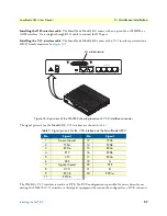
Figure 11. Rear view showing location of Ethernet and FXS connectors (SmartNode 4834 shown)
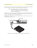
Figure 12. Analog FXS connection
Analog ports (FXS)
1 or 2
Ethernet connectors
Phone
Ring (-) 3
Tip (+) 4
3 Ring (-)
4 Tip (+)
RJ-11, male
RJ-11, male


