Installing the SmartNode device
30
SmartNode 5541 & 4141 Series User Manual
3
• SmartNode Installation
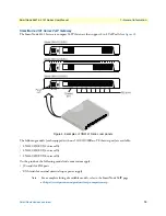
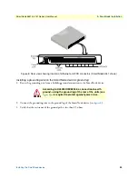
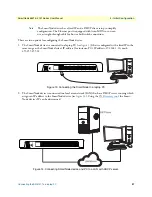
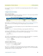
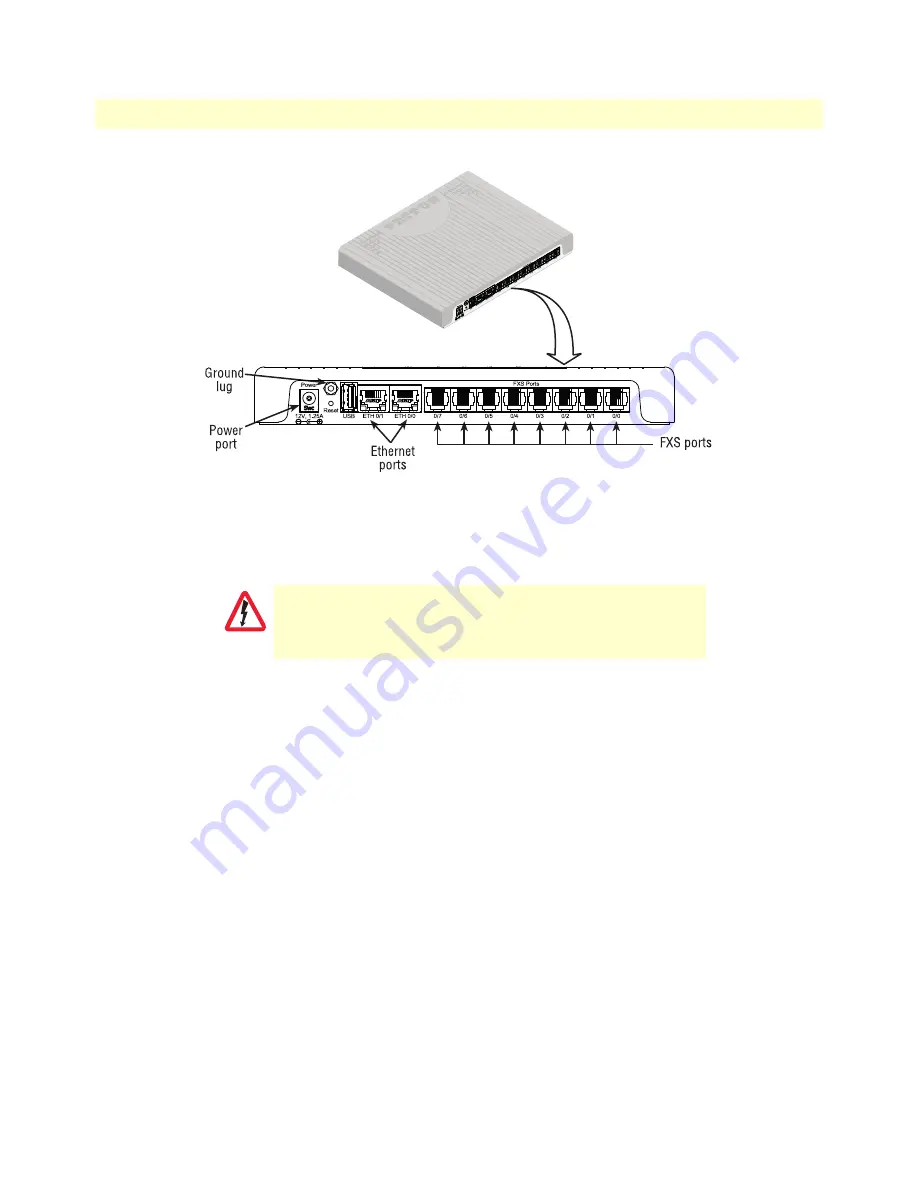
Figure 8. Rear view showing location of Ethernet and FXS connectors (SmartNode 5541 shown)
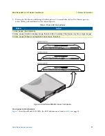
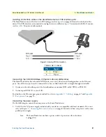
Installing a grounding wire on the SmartNode device’s ground lug
1.
Route the grounding wire from a building ground connection to the SmartNode device.
2.
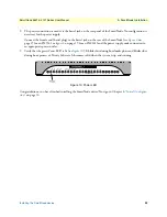
Connect the grounding wire to the ground lug of the SmartNode device (see
).
3.
Verify that the resistance of the ground path is less than 0.5 ohms.
According to UL60950/IEC62368, a connection to earth
ground—using the ground lug at the rear of the units (see
—is required to protect against power cross.
WARNING
Содержание SmartNode 4141 Series
Страница 49: ...49 Appendix C Cabling Chapter contents Introduction 50 Ethernet 50 Analog FXS 51...
Страница 52: ...52 Appendix D Port pin outs Chapter contents Introduction 53 Ethernet 53 FXS port 53...
Страница 54: ...FXS port 54 SmartNode 5541 4141 Series User Manual D Port pin outs Figure 18 RJ 11 pinout diagram...
Страница 55: ...55 Appendix E SmartNode Device Factory Configuration Chapter contents Introduction 56...

