Installing the SmartNode device
28
SmartNode 5541 & 4141 Series User Manual
3
• SmartNode Installation
•
IP addresses and/or URL of SIP servers or Internet telephony services (if used)
•
Login and password for PPPoE Access
•
Login and Password for SIP based telephony services
•
IP addresses of central TFTP server used for configuration upload and download (optional)
Software tools
You will need a PC (or equivalent) with Windows Telnet or a program such as Tera Term Pro or Putty to con-
figure the software on your SmartNode device. Also you may use your web browser to configure the unit. The
WebWizard in this case reduces time to get your unit up and running. See more details on
Power source
If you suspect that your AC power is not reliable, for example if room lights flicker often or there is machinery
with large motors nearby, have a qualified professional test the power. Patton recommends that you include an
uninterruptible power supply (UPS) in the installation to ensure that VoIP service is not impaired if the power
fails.
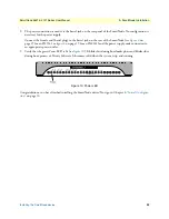
Installing the SmartNode device
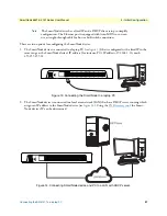
SmartNode device installation consists of the following:
•
Placing the device at the desired installation location (see section
“Placing the SmartNode device”
•
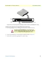
Installing the grounding wire (if your SmartNode device came equipped with a surge protector), and install-
ing interface and power cables (see section
When you finish installing the SmartNode device, go to Chapter 4,
Placing the SmartNode device
Place the SmartNode device on a desktop or similar sturdy, flat surface. Allow sufficient space at the rear of the
chassis for cable connections. Additionally, you should consider the need to access the unit for future upgrades
and maintenance.
To prevent overheating and damaging the unit, proper ventilation is required when placing the device. The
device should be installed in a dry environment with sufficient space to allow air circulation for cooling.
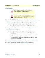
Do not stack multiple SmartNode devices directly on top of one another, and do not
place items on top of the device. If you will be installing equipment above the Smart-
Node device, leave at least 2 inches (5 cm) of clearance between the devices.
Furthermore, leave at least 2 inches (5 cm) to the left, right, front, and rear of the
SmartNode device for proper ventilation.
CAUTION
Содержание SmartNode 4141 Series
Страница 49: ...49 Appendix C Cabling Chapter contents Introduction 50 Ethernet 50 Analog FXS 51...
Страница 52: ...52 Appendix D Port pin outs Chapter contents Introduction 53 Ethernet 53 FXS port 53...
Страница 54: ...FXS port 54 SmartNode 5541 4141 Series User Manual D Port pin outs Figure 18 RJ 11 pinout diagram...
Страница 55: ...55 Appendix E SmartNode Device Factory Configuration Chapter contents Introduction 56...

