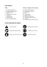
SETTING UP
Warning! Risk
of injury!
Before performing any operation unplug the power cord from
the wall socket.
Information on the blades
The machine is designed for using two replacement
planer
blades with
82
mm length
.
The planer blades
have two blade
edges and are reversible
.
When both cutting edges are dull the blades must be replaced.
P
laner blades
may not be resharpened!
Warning! Risk of injury!
When mounting the blades
wear protective gloves
and do not
touch the edges. The blades are
very sharp.
B
lade disassembly (see Picture
A)
When replacing a blade, always replace or reverse both blades at the same time. Otherwise imbalance
can cause vibrations and reduce the service life of the machine.
Do not release the two hex screws (
11
).
They are used to adjust the height of the blade assembly.
•
Using the supplied wrench (
6
), turn
the
three bolts (
10
) in clockwise direction to loosen the blade
holder (
12
). When turned clockwise the bolts thread into the blade holder, thus releasing pressure
on the spindle drum and allowing the blade
to be removed.
•
Use a piece of wood to slide the blade
(13)
lengthwise out of the blade holder.
There is a groove (
16
)
in the plastic body for this purpose.
•
Clean the blade
clamping elements and the blade, if required.
•
Turn the cutter spindle (
15
) half turn and repeat the procedure to disassemble the second blade
(eventually leave this second side as a template and disassemble it only after assembling the first
side).
Blade assembly and adjustment
(see Picture A)
•
Assemble
the planer blade in
reversed order. Ensure that it is seated properly between the blade
holder (
12
) and the press plate
(
14
)
and is
aligned with the side
edge of the rear base plate
(
17
)
.
For
correct lateral alignment, place a straight piece of wood along the side edge of front and rear base
plates
(
17, 19
)
and slide the blade against this
straight piece of wood so that the blade
aligns flush
with both plates.
•
Turn the three bolts (
10
) anti
-
clockwise to secure the blade holder
.
Only snug the
b
olts for now.
•
To adjust the height of the blade, set the depth knob (1) to zero and place a straight object onto
the
rear base plate
(17)
.
Use the allen key (
7
) to turn
the
hex screws (
11
) which adjust the position of
blade holder
(12). The blade must
be just
touching
the straight object
on the base
(17)
.
•
Turn the three bolts (
10
) anti
-
clockwise firmly to secure the blade holder in place.
•
Turn the cutter spindle (
15
)
another half turn and repeat
the procedure to assemble and adjust the
second
blade
.
Warning! Before starting the planer, verify that the bolts of the blade holder are well
tightened and the blades do not graze.
Planing depth
adjustment
The depth of cut can be adjusted variably from 0
–
2 mm with adjustment knob (
1
), using the depth scale
at the knob base.
29
Содержание EH0650
Страница 2: ...2...
Страница 3: ...A B 3...

