background image


10 

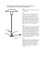
ASSEMBLY INSTRUCTIONS FIXED BASE MODELS 


PH-45-FB-LP     (Liquid Propane), PH-50-FB-N        (Natural Gas),  
PH-45-FB-D-LP (Liquid Propane), PH-50-FB-D-NG (Natural Gas) 
Fixed base model for permanent mounting to deck or patio “D” indicates heater with 
direct light electronic ignition, no standing pilot.  Requires switched 24 Volt power 
supply to heater.) 

       Step 1 

                                                       Determine a safe, level and stable location for the base 

mount to be installed.


Step 2


Secure the base to the deck or concrete pad with 
appropriate fasteners.  Use all three mounting holes.  Use 
corrosion resistant hardware.  Inspect condition of 
mounting studs before use of the heater each season.  
Replace if rusty, loose, or shows signs of damage.  Use of 
through bolts is recommended on wood decks. 
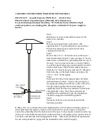
Step 3


Remove the 3/8” x 1” bolt in the base of the heater head 
and set aside. (Figure 2 previous page 7). Secure heater 
head to flexible hose protruding from the top of the post.  
Use two pipe wrenches to securely tighten.  A suitably 
approved gas pipe sealant must be used for all gas 
connections.  Slide head assembly into post. Align the 3/8” 
hole in the post with the 3/8” threaded hole in the base of 
the heater head, and replace the 3/8” x 1” bolt.  Secure 
tightly. 
Step 4 
Slide the decorative cover onto the post from the bottom. 
Place the post into the basemount “T” and slide the 
decorative cover down over the post retainer.  Connect gas 
supply to the nipple protruding from the lower side of the 
tube. 
Step 5 
Secure the reflector to the heater head with the hardware 
provided. 

CAUTION

: Gas supply and electrical supply are to be according to all local and applicable 

codes.  Only those individuals licensed and qualified in the installation of gas fired heating 
appliances are to install this appliance. 
 
D-Direct Light:  If your heater has been supplied with a direct light electronic ignition, 
connect your switched 24 V power supply to the spade connectors protruding from the 
bottom end of the post. Connect spade connectors at the top of the post to the marked 
connections on the heater head.  All supply wiring must be done in accordance will national, 
local and applicable codes.   Only those qualified and experienced in such wiring should be 
engaged for the installation of the electrical supply. 
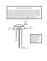
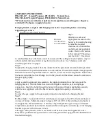
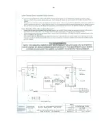
Dec k or
concrete
pad

Gas  shutoff
by others

Underground
gas supply

Содержание PH series

Страница 1: ...tentivement les instructions d installation de fonctionnement et d entretien avant de proc der l installation ou l entretien de cet quipement This manual applies to the following Patio Plus models PH...

Страница 2: ...ustment alteration service or maintenance can cause injury property damage or death Read the complete installation manual and all warning labels on the appliance before installation or servicing this...

Страница 3: ...maintained Combustible materials are considered to be wood compressed paper plant fibers or other materials capable of being ignited and burned Such materials shall be considered combustible even thou...

Страница 4: ...atios must be large enough to meet the clearance to combustibles and ventilation requirements as provided for in all applicable codes For very small enclosed patios Patio Plus heaters may not be suita...

Страница 5: ...tach regulator to your L P tank or gas line securely Leave the L P tank outside the cabinet for the testing procedure 3 Open the valve of the L P tank or turn main gas valve to heater ON then leave th...

Страница 6: ...be used on L P gas special precautions should be observed when handling L P cylinders Remember that this is gas and under pressure which must be handled with care Ask your L P gas dealer to show you t...

Страница 7: ...ulator assembly Always store L P cylinders in a well ventilated space If you intend to store the heater indoors disconnect the L P cylinder and store it outside Disconnected cylinders must have a thre...

Страница 8: ...the 3 post The top of the post can be identified by the 3 8 hole being at the top end Line up the 3 8 hole in the post with the 3 8 hole in the base of the heater head and replace the previously remo...

Страница 9: ...de the decorative cover onto the post from the bottom Place the post into the basemount T on the weighted base and slide the decorative cover down over the post retainer Connect gas supply to nipple p...

Страница 10: ...y into post Align the 3 8 hole in the post with the 3 8 threaded hole in the base of the heater head and replace the 3 8 x 1 bolt Secure tightly Step 4 Slide the decorative cover onto the post from th...

Страница 11: ...f the heater head and replace the 3 8 x 1 bolt Secure tightly Step 4 Insert post into the ground support pipe and fasten with hardware provided Connect the gas supply to the nipple protruding from the...

Страница 12: ...sition Ensure that the heater is installed so that it hangs level to the ground and that stress cannot be created on the gas supply piping Step 3 Apply a suitably approved pipe sealant to the nipple p...

Страница 13: ...b will be in an immovable position Wait 90 seconds and the thermocouple will cool and knob will be released to re light pilot To Light Main Burner except Direct Lite After pilot is lit wait 30 seconds...

Страница 14: ...e has no pilot Defective thermopile Defective gas valve Dirty pilot Replace thermopile Replace gas valve Clean pilot Main Burner won t light No 24 Volt power to unit Low gas pressure Blockage in orifi...

Страница 15: ...ds a 3 YEAR warranty from the date of purchase to the original purchaser of this product against manufacturing defects in material and workmanship If this product fails to operate because of a manufac...

Страница 16: ...16...

Страница 17: ...17...

Страница 18: ...18...

Страница 19: ...19...

Страница 20: ...20...

Отзывы: