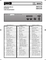
background image

SERIE 5000

5

CONNECTIONS

3

CONNESSIONI

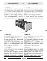
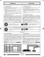
3.1 CRITERI GENERALI

Per un corretto funzionamento dell’apparecchio è opportuno osservare

alcuni criteri di massima nell’esecuzione dei collegamenti:

• evitare  il posizionamento di cavi e di  microfoni sul mobile

dell’apparecchio.

• evitare di  stendere le linee di  segnale parallele a quelle  di rete;

osservare una distanza minima di 30/40 cm.

• posizionare le linee di ingresso e le linee di uscita distanti tra loro.

• posizionare i microfoni al di fuori dell’angolo di radiazione dei diffusori

sonori  per evitare il fenomeno di reazione acustica (effetto Larsen).

3.1 GENERAL FEATURES

For proper unit operation, use the following instructions when making

the connections:

• Do not place cables or microphones on the unit cabinet;

• Do not lay signal lines parallel to power lines; ensure a minimum

distance of 30/40 cm between them;

• Keep input lines and the output lines far apart;

• Keep the microphones outside the operating span of the speakers to

avoid acoustic feedback (Larsen effect).

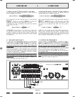
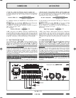
3.3 INGRESSO TELEFONICO

L’apparecchio è predisposto per il collegamento ad un sistema telefonico

tramite la morsettiera “

TEL

” [

10

]. Tale ingresso è bilanciato a

trasformatore, possiede un proprio controllo di livello - “

LEV.

”


[

11

] - ed è

dotato di circuito VOX per la diffusione dei messaggi con priorità più

elevata rispetto a qualsiasi altro ingresso.
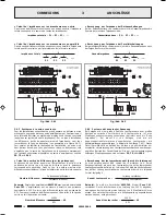
L’ingresso telefonico consente inoltre il collegamento dell’apparecchio alle

basi preamplificate PASO mod. 

B611

. Per questo è necessario rimuovere

lo spinotto pentapolare DIN dal cavo della base e con i fili realizzare i

collegamenti illustrati in fig. 3.3.1. Tale configurazione consente anche

l’invio di un segnale di preavviso (vedi par. 3.5).

IMPORTANTE

: per questo tipo di collegamento è INDISPENSABILE

chiudere tramite un ponticello i contatti [

G

] e [

COM

] della morsettiera

“

TEL

” [

10

].

3.3 TELEPHONE INPUT

The equipment has provisions for connection of a telephone system by

means of the “

TEL

” terminal strip [

10

]. This input is balanced by a

transformer, has its own level control - “

LEV.

” 


[

11

] - and is equipped with

a VOX circuit for broadcasting messages with a higher priority level than

any other input.

The telephone input also enables the equipment to be connected to the

PASO mod. 

B611

 preamplified bases. To do this, it is necessary to remove

the five-pole DIN plug from the cable on the base and use the wires to

make the connections illustrated in Figure 3.3.1. This configuration also

enables a warning signal to be sent (see point 3.5).

IMPORTANT

: For this type of connection it is ESSENTIAL to close the

contacts [

G

] and [

COM

] of the “

TEL

” terminal strip [

10

] with a jumper.

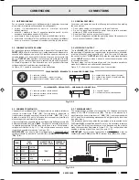
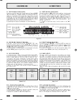
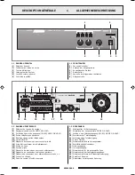
3.2 INGRESSO/USCITA DI LINEA

Sul pannello posteriore dell’apparecchio è disponibile l’ingresso di linea

INPUT

 [

15

] dell’unità di potenza: per il collegamento sono disponibili, a

seconda delle esigenze, una presa XLR femmina oppure una presa per

spinotto jack da 1/4”. La spina XLR maschio e la presa  per spinotto jack

da 1/4”

 OUTPUT

 [

16

] riportano lo stesso segnale presente alla presa

INPUT

, per un facile collegamento in cascata tra più unità di potenza.

Lo stadio d’ingresso è di tipo bilanciato, per cui è possibile effettuare

collegamenti sia di tipo bilanciato che sbilanciato.

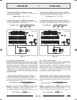
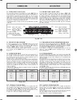
La figura 3.2.1 riporta le connessioni, viste dall’esterno.

 Fig. 3.2.1

1

= schermo / shield

2

= segnale (lato caldo) / signal (hot side)

3

= segnale (lato freddo) / signal (cold side)

= segnale (lato caldo) / signal (hot side)

= segnale (lato freddo) / signal (cold side)

= schermo / shield

COLLEGAMENTO BILANCIATO - BALANCED CONNECTION

1

= schermo e massa / shield and 

GND

2

= schermo e massa / shield and 

GND

3

= segnale / signal

= segnale / signal

= schermo e massa / shield and 

GND

3.2 LINE INPUT/OUTPUT

The line 

INPUT 

[

15

] for the power unit is situated on the rear panel of

the equipment. Depending on requirements, two sockets are available:

a female XLR socket and a socket for a ¼" jack. The male XLR plug and

the socket for the ¼" 

OUTPUT 

jack [

16

] relay the same signal available

on the 

INPUT 

socket, to make it easier to connect several power units

in cascade formation.

The input stage is of the balanced type, and it is therefore possible to

make both balanced and unbalanced connections.

Figure 3.2.1 shows the connections, seen from outside.

COLLEGAMENTO SBILANCIATO - UNBALANCED CONNECTION

 Fig. 3.3.1

.

S

O

P

O

V

A

C

E

L

B

A

C

A

R

E

I

T

T

E

S

R

O

M

P

I

R

T

S

L

A

N

I

M

R

E

T

E

L

A

N

I

M

R

E

T

L

A

N

I

M

R

E

T

1

O

M

R

E

H

C

S

D

L

E

I

H

S

"

L

E

T

"

[

G

]

2

O

R

E

N

K

C

A

L

B

[

M

O

C

]

3

O

C

N

A

I

B

E

T

I

H

W

[

T

O

H

]

4

O

S

S

O

R

D

E

R

"

Y

T

I

R

O

I

R

P

"

[

+

]

5

E

D

R

E

V

N

E

E

R

G

[

P

]

11-542.p65

26/10/01, 14.20

5

Содержание AW5120

Страница 1: ...riority and warning signal 6 3 6 Power outputs 6 3 6 1 Low impedance systems 6 Calculating the impedance value in series connections 7 Calculating the impedance value in parallel connection 7 3 6 2 Constant voltage systems 7 Determining the number of speakers through power values 7 Determining the number of speakers through impedance 8 3 7 Selecting the listening areas 8 4 Operation 4 1 Power on 9...

Страница 2: ...arschuwingssignaal 24 3 6 Vermogensuitgangen 24 3 6 1 Systemen met een lage impedantie 24 Berekening van de impedantie bij serieschakeling 25 Berekening van de impedantie bij parallelschakeling 25 3 6 2 Constante spanningssystemen 25 Berekening van het aantal klankverspreiders via de kracht 25 Berekening van het aantal klankverspreiders via de impedanties 26 3 7 Selectie van luisterzones 26 4 Gebr...

Страница 3: ...1 FRONT PANEL 1 Zone selection switches 2 Output level indicator 3 ON OFF signalling lamp 4 Mains switch 5 General volume control 6 Tone controls 1 2 REAR PANEL 7 Mains voltage selector switch 8 MUSIC ON HOLD output level adjustment 9 MUSIC ON HOLD line and power outputs 1W 8Ω 10 Balanced telephone input 11 Telephone input level adjustment 12 Chime ON OFF 13 Terminal strip for precedence contact 1...

Страница 4: ...re altre apparecchiature per la sola funzione di schermatura dei segnali a basso livello questa presa non deve essere utilizzata per il collegamento di sicurezza del telaio alla terra Fig 2 1 1 2 1 INSTALLATION All PASO equipment is manufactured in accordance with the most stringent international safety standards and in compliance with European Community requisites In order to use the equipment co...

Страница 5: ...e telephone input also enables the equipment to be connected to the PASO mod B611 preamplified bases To do this it is necessary to remove the five pole DIN plug from the cable on the base and use the wires to make the connections illustrated in Figure 3 3 1 This configuration also enables a warning signal to be sent see point 3 5 IMPORTANT For this type of connection it is ESSENTIAL to close the c...

Страница 6: ...all azione di precedenza microfonica o telefonica In particolare l uscita bilanciata a trasformatore morsetti 1 2 3 di fig 3 4 1 puo essere utilizzata per il pilotaggio di un ulteriore amplificatore di un centralino telefonico od altro l uscita di potenza morsetti 3 4 di fig 3 4 1 e in grado di pilotare direttamente un piccolo altoparlante monitor da 8 Ω con potenza massima di 1 W É possibile rego...

Страница 7: ...rmula 1 1 Z1 1 Z2 1 Z3 impedenza totale Calculating the impedance value in series connections In the case of loudspeakers connected to one another in series the total impedance is the sum of the single impedance values Total impedance Z1 Z2 Z3 Calculating the impedance value in parallel connection In the event of loudspeakers connected in parallel to one another the total impedance can be calculat...

Страница 8: ...minal strip 18 by means of a length of wire An example of connection to three broadcasting zones with a line voltage of 100 V is shown in Figure 3 7 1 Fig 3 7 1 Calcolo del numero di diffusori tramite le impedenze Se il dato disponibile è l impedenza del diffusore il numero massimo di diffusori collegabili ad una linea è dove l impedenza nominale dell amplificatore è ricavabile dalla tabella 3 6 1...

Страница 9: ...de it It should be pointed out lastly that models AW5120 and AW5240 are equipped with cooling fans with automatic control of the speed in relation to the temperature of the heat sink to which the power devices are applied 4 1 POWER ON Before starting up the equipment make sure that all the connections required for completing the system have been made and that all the settings for correct operation...

Страница 10: ... e l b e r T t u p n i e n i L a e n i l i d o s s e r g n I o s s e r g n i a z n e d e p m i à t i l i b i s n e S V m 0 5 2 k 7 4 Ω e c n a d e p m i y t i v i t i s n e s t u p n I o b r u t s i d e l a n g e s o t r o p p a R B d 4 8 o i t a r N S a z n e u q e r f n i a t s o p s i R B d 3 0 z H 0 0 0 2 2 0 4 e s n o p s e r y c n e u q e r F a z n e d e c e r p e n o i z a u n e t t A B d 0...

Страница 11: ... u c r i c e m e i s s A 1 1 7 2 9 9 y l b m e s s a t i u c r i c e n o h p H O M e r o t a t n e m i l a o t i u c r i c e m e i s s A 3 1 7 2 9 9 2 1 7 2 9 9 y l b m e s s a t i u c r i c y l p p u s r e w o P N O D N I D o t i u c r i c e m e i s s A 8 1 7 2 9 9 y l b m e s s a t i u c r i c E M I H C e t i c s u e r e i t t e s r o m e m e i s s A 9 1 7 2 9 9 y l b m e s s a l a n i m r e t t...

Страница 12: ... 2 ALL OUTPUT LEVEL POWER MASTER VOLUME 10 0 TREBLE 0 10 10 BASS 10 10 1 2 4 5 6 3 0 ALLGEMEINE BESCHREIBUNG 1 1 FRONTPANEEL 1 Zonenwahlschalter 2 Anzeige der Ausgangsstufe 3 Kontrollleuchte Ein Aus 4 Netzschalter 5 Kontrolle der allgemeinen Lautstärke 6 Klangkontrolle 1 2 RÜCKPANEEL 7 Wählschalter für Netzspannung 8 Einstellung der Ausgangsstufe MUSIC ON HOLD 9 Leitungs und Leistungsausgang 1W 8Ω...

Страница 13: ...ils à la connexion de masse du châssis 20 seulement pour la fonction de protection des signaux à bas niveau cette prise ne doit pas être utilisée pour la connexion de sécurité du châssis à la terre Fig Abb 2 1 1 2 2 EINSPEISUNG Das Gerät ist für den Betrieb mit einer Netzspannung von 230 V 10 50 60 Hz ausgelegt Es besteht auch die Möglichkeit das Gerät mit einer Netzspannung von 115 V 10 50 60 Hz ...

Страница 14: ... Signal warme Seite 2 signal côté froid Signal kalte Seite 3 blindage Abschirmung BRANCHEMENT ÉQUILIBRÉE SYMMETRISCHE ANSCHLÜSSE 1 blindage et masse Abschirmung und Erdung 2 blindage et masse Abschirmung und Erdung 3 signal Signal 1 signal Signal 2 blindage et masse Abschirmung und Erdung BRANCHEMENT DÉSÉQUILIBRÉE ASYMMETRISCHE ANSCHLÜSSE Fig Abb 3 3 1 ANSCHLÜSSE 3 1 ALLGEMEINE HINWEISE Für einen ...

Страница 15: ...UND VORANKÜNDIGUNGSSIGNAL Bei Schließen aller Kontakte des Klemmenbretts PRIORITY 13 wird das Signal an der Buchse INPUT 15 stummgeschaltet das Schließen des Kontakts generiert das Zweiton Vorankündigungssignal CHIME der Wählschalter CHIME 12 ist in der Stellung ON Es ist möglich die Stufe des Vorankündigungssignals mit Hilfe des halbfesten Trimmers VR301 auf dem Schaltkreis Priority zu ändern sie...

Страница 16: ...tensions constantes disponibles en sortie d amplificateur sont de 50 70 et 100 V Fig Abb 3 6 1 Fig Abb 3 6 2 16Ω Ω Ω Ω Ω 16Ω Ω Ω Ω Ω 20W 20W ANSCHLÜSSE Berechnung der Impedanz bei Reihenschaltungen Bei der Reihenschaltung von Lautsprechern ist die Gesamtimpedanz die Summe der einzelnen Impedanzwerte Gesamtimpedanz Z1 Z2 Z3 Berechnung der Impedanz bei Parallelschaltungen Bei parallelgeschalteten La...

Страница 17: ...est inférieure à la puissance nominale de l amplificateur 3 7 AUSWAHL DER KLANGZONE Die Verstärker der Serie 5000 verfügen über die Möglichkeit unabhängig mit Hilfe der Schalter ZONE 1 ZONE 2 e ZONE 3 1 bis zu drei Klangzonen zu ein bzw auszuschalten In diesem Fall müssen die drei Lautsprecherzonen an das Klemmenbrett 17 angeschlossen werden wobei die maximale für das Gerät zulässige Nennleistung ...

Страница 18: ...température du dissipateur sur lequel sont appliqués les dispositifs de puissance GEBRAÜCH DES GERATES 4 1 EINSCHALTEN Vor Einschalten des Geräts muss sichergestellt werden dass alle für die komplette Installation der Anlage erforderlichen Anschlüsse hergestellt und die Betriebseinstellungen vorgenommen wurden Den Netzschalter 4 auf ON schalten Die POWER Leuchtanzeige 3 bestätigt das Einschalten d...

Страница 19: ...i T s u g i A z H k 0 1 B d 1 1 e n ö t h c o H g n a g n i e s g n u t i e L e n g i l e d e é r t n E e c n a d é p m i é t i l i b i s n e S V m 0 5 2 k 7 4 Ω z n a d e p m I t i e k h c i l d n i f p m E t i u r b l a n g i s t r o p p a R B d 4 8 g n u r ö t S l a n g i S n o v s i n t l ä h r e V e c n e u q é r f n e e s n o p é R B d 3 0 z H 0 0 0 2 2 0 4 g n a g z n e u q e r F é t i r o ...

Страница 20: ...l e T H O M s i e r k t l a h c S t i e h n i E r u e t a t n e m i l a t i u c r i c e p u o r G 3 1 7 2 9 9 2 1 7 2 9 9 s i e r k t l a h c s s g n u g r o s r e V t i e h n i E G N O D G N I D t i u c r i c e p u o r G 8 1 7 2 9 9 G N O G g n u t l a h c S t i e h n i E s e i t r o s s r e i n r o b e p u o r G 9 1 7 2 9 9 e g n ä g s u A r e t t e r b n e m m e l K t i e h n i E s e n o z e i ...

Страница 21: ...ESCRIPCIÓN GENERAL 1 1 PANEL FRONTAL 1 Selectores de las zonas 2 Visualizador del nivel de salida 3 Chivato de encendido 4 Interruptor de red 5 Mando de volumen general 6 Mandos de tono 1 2 PANEL TRASERO 7 Selector de la tensión de red 8 Regulación nivel salida MUSIC ON HOLD 9 Salidas de línea y de potencia 1W 8Ω MUSIC ON HOLD 10 Entrada telefónica balanceada 11 Regulación nivel entrada telefónica...

Страница 22: ...ordt met als enige functie dat signalen met een laagniveau worden afgeschermd dit stroomafnamepunt mag niet gebruikt worden voor de veiligheidsverbindingen tussen frame en aarding Afb Fig 2 1 1 2 2 ALIMENTACIÓN Este aparato está predispuesto para el funcionamiento con tensión de red a 230 V 10 50 60 Hz Es posible utilizar el aparato también con una tensión de red de 115 V 10 50 60 Hz con tal fin e...

Страница 23: ...o frío 3 afscherming blindaje GEBALANCEERDE TYPE TIPO BALANCEADO 1 afscherming en massa blindaje y masa 2 afscherming en massa blindaje y masa 3 signaal señal 1 signaal señal 2 afscherming en massa blindaje y masa NIET GEBALANCEERDE TYPE TIPO NO BALANCEADO Afb Fig 3 3 1 3 3 ENTRADA TELEFÓNICA El aparato está predispuesto para la conexión a un sistema telefónico mediante el terminal de conexión TEL...

Страница 24: ...luidsprekers nodig zijn kan de verbindingslijn worden aangesloten tussen de gewone klem 0 en de bus 8 Ω Ω Ω Ω Ω van de klemmenstrook 18 De aansluiting van de luidsprekers serieel parallel of gemengd moet een impedantie opbrengen van tenminste 8 Ω Op afbeelding 3 6 1 staat een voorbeeld van een aansluiting 3 4 SALIDAS MUSIC ON HOLD MOH En estos bornes 9 hay disponible la señal presente en la entrad...

Страница 25: ...te spanningen liggen tussen de 50 70 en 100 V Afb Fig 3 6 1 Afb Fig 3 6 2 16Ω Ω Ω Ω Ω 16Ω Ω Ω Ω Ω 20W 20W CONEXIONES Cálculo de las impedancias en las conexiones en serie En el caso de difusores conectados in serie entre ellos la impedancia total es la suma de las impedancias individuales impedancia total Z1 Z2 Z3 Cálculo de las impedancias en las conexiones en paralelo En el caso de difusores con...

Страница 26: ... de manera independiente hasta tres zonas de difusión mediante los interruptores ZONE 1 ZONE 2 y ZONE 3 1 En este caso las tres zonas de difusores se deben conectar a la bornera 17 teniendo siempre en cuenta la carga nominal máxima admitida por el aparato Además es posible seleccionar contemporáneamente todas las zonas de escucha mediante el interruptor ALL Las selecciones efectuadas mediante los ...

Страница 27: ...tilator met automatische regeling van de snelheid op basis van de temperatuur van de dissipator waarop de vermogensystemen zijn aangebracht 4 1 ENCENDIDO Antes de poner en función el aparato se debe comprobar que se haya realizado todas las conexiones necesarias para completar la instalación y efectuado las configuraciones de funcionamiento Pongan el interruptor de red 4 en la posición ON La luz i...

Страница 28: ...1 1 s o d u g a s o n o T a e n í l e d a d a r t n E g n a g n i n j i L e i t n a d e p m i d i e h g i l e o v e G V m 0 5 2 k 7 4 Ω a i c n a d e p m i d a d i l i b i s n e S g n i r o t s l a a n g i s g n i d u o h r e V B d 4 8 o d i u r l a ñ e s n ó i c a l e R e i t n e u q e r f n i s n o p s e R B d 3 0 z H 0 0 0 2 2 0 4 a i c n e u c e r f n e a t s e u p s e R g n i p m e d s t i e ...

Страница 29: ... d i e h n e e s g n i d e o v t i u c r i c l e t s n e m a S 3 1 7 2 9 9 2 1 7 2 9 9 r o d a t n e m i l a o t i u c r i c o t n u j n o C t i u c r i c G N O D G N I D l e t s n e m a S 8 1 7 2 9 9 N O D N I D o t i u c r i c o t n u j n o C n e g n a g t i u n e d r o b n e m m e l k l e t s n e m a S 9 1 7 2 9 9 s a d i l a s s a r e n r o b o t n u j n o C g n a g t i u e n o z n e d r o b n...

Страница 30: ...nstant et sans préavis aucun MERKE In der Überzeugung die eigenen Produkte beständig verbessern zu wollen behält sich PASO S p A das Recht vor jederzeit und ohne Vorankündigung Änderungen an technischen Zeichnungen und Merkmalen vorzunehmem OPMERKING Aangezien PASO S p A voortdurend verbeteringen aanbrengt aan haar producten behoudt zij zich het recht voor op ieder moment zonder voorbericht de tek...

Отзывы: