background image

6.

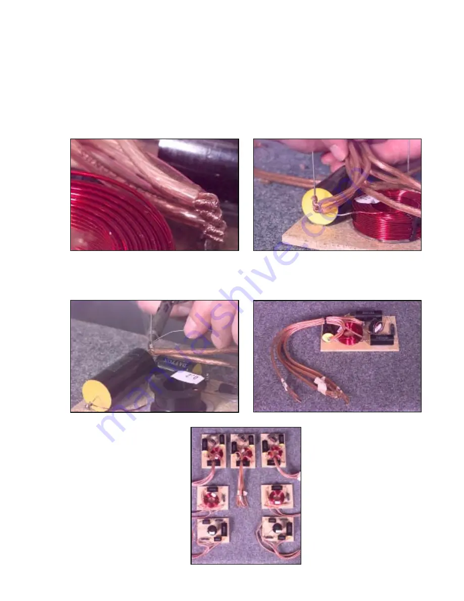
Cut the supplied wire into 22 pieces approximately 13-1/2"long.  Strip the insulation on all wires back
about 1/2".  Do not tin the wire leads at this time!

7.

While observing proper polarity attach all input and driver wires to their respective mounting posts.  Example:
To attach the input wire, take the positive (+) input wire and wrap it around the “IN+” post.  Next, take the
negative (-) input wire and wrap it around the ground “GND”post.  To attach the tweeter wire, take the positive
(+) tweeter wire and wrap it around the “T+” post.  Next, take the negative (-) tweeter wire and wrap it around
the ground “GND” post.  The L/Ctr/R speakers use two woofers, so you need to attach two woofer leads to
each crossover.  The surround speakers use two tweeters so you need to attach two tweeter leads to the high
pass surround crossovers.  Note: Keep in mind that the ground post on each L/Ctr/R crossover will have four
(4) wires connected to it so you should start low and connect one at a time. Repeat this step for the woofers
and other crossovers.  Again, it is very important to observe the proper polarity!

8.

Solder all wire and post connections.  Using wire cutters, trim off any excess mounting posts and component
leads.  At this point, it is a good idea to label each wire to ensure proper hook-up.  Masking tape and a
marker will work fine.

Page 5

Содержание LDC6

Страница 1: ...ntical timbe content for the front of the home theater system Because center channels are usually placed on top of TVs its driver layout is acoustically oriented for horizontal placement The system al...

Страница 2: ...sistors 005 2 5 Mills 2 Ohm 12W Non Inductive Resistors 005 4 2 Mills 4 Ohm 12W Non Inductive Resistors 005 5 3 Mills 5 Ohm 12W Non Inductive Resistors 999 212 3 4 x 6 L Ctr R Xover boards 999 213 4 4...

Страница 3: ...mproperly wired network can damage your receiver or amp lifier Please double and triple check all values and wiring before installing the crossovers in the cabinets Tips on assembling the crossovers 1...

Страница 4: ...respective drawings Note Do not trim the component leads at this time The drawings show the locations where the input and output driver wires will connect Fig 3 4 At these locations bend the componen...

Страница 5: ...wrap it around the ground GND post The L Ctr R speakers use two woofers so you need to attach two woofer leads to each crossover The surround speakers use two tweeters so you need to attach two tweet...

Страница 6: ...behind the tweeter hole Feed the input wire through the opening in the back of the cabinet Remove excess wire and then strip and tin the wire ends Solder wire ends to the terminal cup while observing...

Страница 7: ...er the bottom of the tweeter hole but this will not effect the mounting of the tweeter Feed the input wires from both crossovers through the back of the cabinet Attach and mount the terminal cup using...

Страница 8: ...iver mounting holes with the predrilled holes Left Center Right Remove excess wire and then strip and tin the wire ends Solder each wire to the appropriate driver terminals while observing proper pola...

Страница 9: ...the tweeters Tighten the screws only until the drivers are flush with the baffle of the cabinet Do not over tighten the screws Page 9 5 Room Placement Room placement for the home theater system is fai...

Страница 10: ...725 Pleasant Valley Drive Springboro Ohio 45066 1158 Phone 937 743 3000 Fax 937 743 1677 E mail sales partsexpress com DISTRIBUTED BY...

Отзывы: