2.
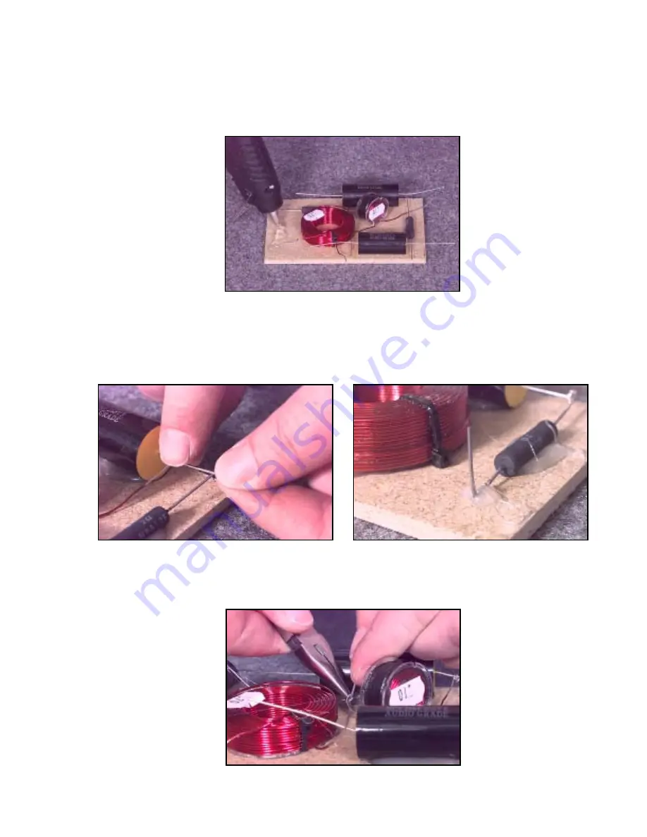
When positioning components try to keep lead lengths to a minimum. Note: The .10mH inductor used
on the L/Ctr/R crossovers should be mounted on its side to minimize the interaction between the two
coils on the board.
3.
Use RTV sealant or hot glue to mount the components to the board. We recommend using hot glue due to
its faster setup time. If you use RTV sealant, you may need to let it setup over night, before proceeding
with the assembly.
4.
Connect all component leads as per their respective drawings. Note: Do not trim the component leads at
this time! The drawings show the locations where the input and output (driver) wires will connect (Fig.3,4).
At these locations, bend the component leads to create mounting posts for the input and output (driver)
wiring. This will make it much easier to terminate the wire, especially the ground connections. You can
secure the “mounting posts” to the board with hot glue or RTV to give the post more stability.
5.
Solder all component connections using silver or electronics grade (60/40) solder. A properly soldered
connection appears shiny and smooth. We recommend using a soldering iron with a wattage rating
between 20-30watts.
Page 4


