


1
Installation
P a r r I n s t r u m e n t C o m p a n y
8
c
haPter
1
Installation
Note:
Some of the following manual sections
contain information in the form of warnings,
cautions and notes that require special at-
tention. Read and follow these instructions
carefully to avoid personal injury and dam-
age to the instrument. Only personnel quali-
fied to do so, should conduct the installation
tasks described in this portion of the manual.
Environmental Conditions
The 6400 Calorimeter is completely assembled and
given a thorough test before it is shipped from the
factory. If the user follows these instructions, instal-
lation of the calorimeter should be completed with
little or no difficulty. If the factory settings are not
disturbed, only minor adjustments will be needed to
adapt the calorimeter to operating conditions in the
user’s laboratory.
This apparatus is to be used indoors. It requires at
least 4 square feet of workspace on a sturdy bench
or table in a well-ventilated area with convenient
access to an electric outlet, running water and a
drain.
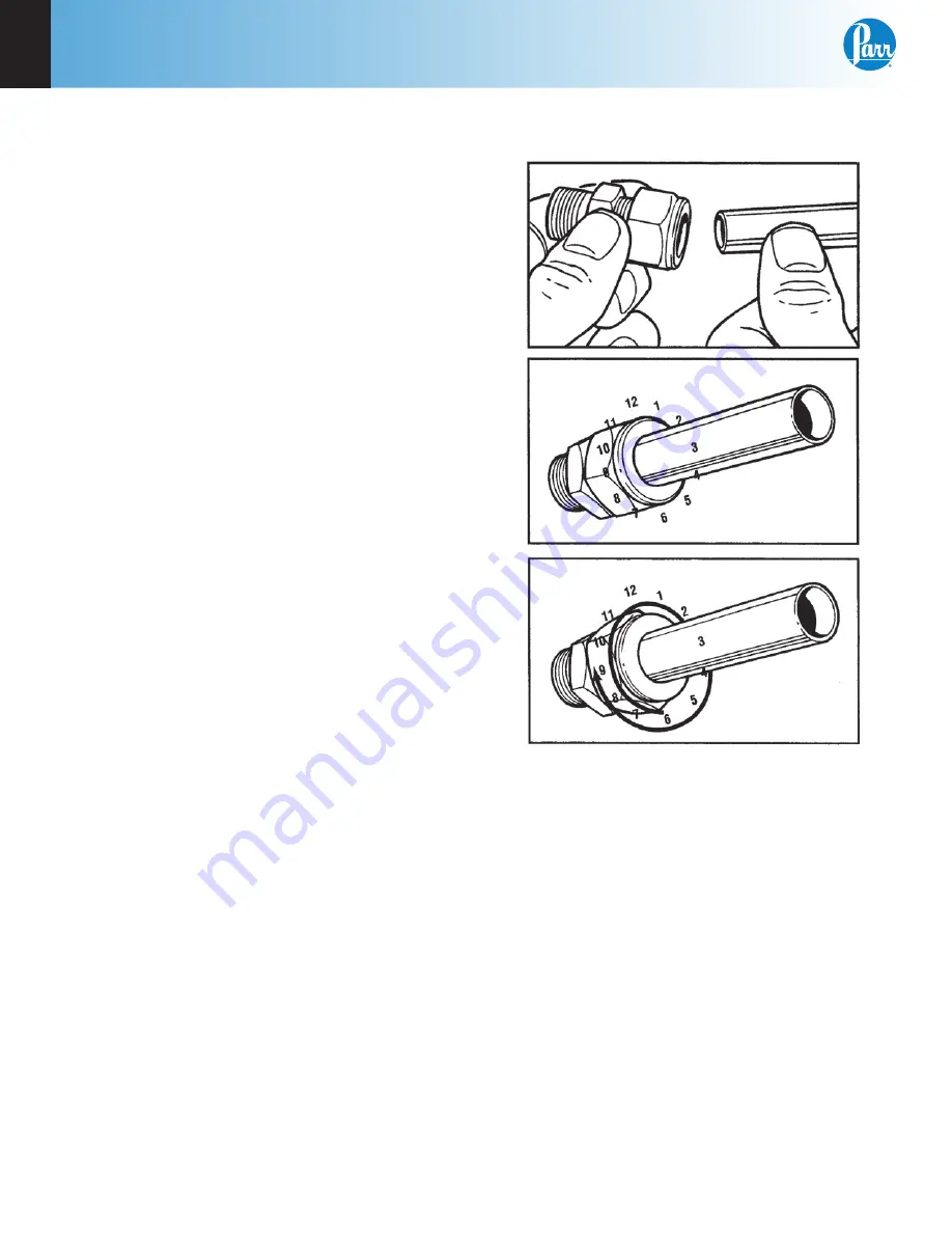
Swagelok Tube Fittings
When Swagelok Tube Fittings are used, the instruc-
tions for installation are:
1. Simply insert the tubing into the Swagelok Tube
Fitting. Make sure that the tubing rests firmly
on the shoulder of the fitting and that the nut is
finger-tight.
2. Before tightening the Swagelok nut, scribe the
nut at the 6 o’clock position.
3. While holding the fitting body steady with a
back-up wrench, tighten the nut 1-1/4 turns.
Watch the scribe mark, make one complete revo-
lution and continue to the 9 o’clock position.
4.
For 3/16” and 4mm or smaller tube fittings, tight
-
en the Swagelok nut 3/4 turns from finger-tight.
Figure 1-1
Swagelok Tube Fittings
Swagelok tubing connections can be disconnected
and retightened many times. The same reliable leak-
proof seal can be obtained every time the connec-
tion is remade using the simple two-step procedure.
1. Insert the tubing with pre-swaged ferrules into
the fitting body until the front ferrule seats.
2. Tighten the nut by hand. Rotate the nut to the
original position with a wrench. An increase in
resistance will be encountered at the original
position. Then tighten slightly with a wrench.
Smaller tube sizes (up to 3/16” or 4mm) take less
tightening to reach the original position than
larger tube sizes.
Содержание 6400
Страница 2: ......
Страница 9: ...w w w p a r r i n s t c o m 7 Notes 6400...
Страница 12: ...1 Installation P a r r I n s t r u m e n t C o m p a n y 10 Figure 1 2 6400 Calorimeter Back Panel...
Страница 17: ...w w w p a r r i n s t c o m 15 Notes 6400 1...
Страница 19: ...w w w p a r r i n s t c o m 17 Notes 6400 2...
Страница 49: ...w w w p a r r i n s t c o m 47 Notes 6400 5...
Страница 71: ...w w w p a r r i n s t c o m 69 Notes 6400 9...
Страница 81: ...w w w p a r r i n s t c o m 79 Notes 6400 12...
Страница 84: ...14 Drawings P a r r I n s t r u m e n t C o m p a n y 82 Chapter 14 Drawings Figure 14 1 1138 Parts Diagram...
Страница 86: ...14 Drawings P a r r I n s t r u m e n t C o m p a n y 84 Figure 14 2 6400 Cutaway Right...
Страница 87: ...Drawings 6400 14 w w w p a r r i n s t c o m 85 Figure 14 3 6400 Cutaway Left...
Страница 88: ...14 Drawings P a r r I n s t r u m e n t C o m p a n y 86 Figure 14 4 6400 Cover Open 1324DD2 Locking Post...
Страница 91: ...Drawings 6400 14 w w w p a r r i n s t c o m 89 Figure 14 8 A1456DD Rinse Valve Assembly...
Страница 92: ...14 Drawings P a r r I n s t r u m e n t C o m p a n y 90 Figure 14 9 6400 Internal Plumbing Diagram...
Страница 93: ...Drawings 6400 14 w w w p a r r i n s t c o m 91 Figure 14 10 6400 Water Tank and Jacket Cooling Solenoid...
Страница 95: ...Drawings 6400 14 w w w p a r r i n s t c o m 93 Figure 14 13 A1268DD Stirrer Motor and Mount...
Страница 96: ...14 Drawings P a r r I n s t r u m e n t C o m p a n y 94 Figure 14 14 6400 Bucket Assembly...
Страница 97: ...Drawings 6400 14 w w w p a r r i n s t c o m 95 Figure 14 15 6400 Air Can Assembly Cutaway Left...
Страница 98: ...14 Drawings P a r r I n s t r u m e n t C o m p a n y 96 Figure 14 16 6400 Air Can Assembly Cutaway Front...
Страница 99: ...Drawings 6400 14 w w w p a r r i n s t c o m 97 Figure 14 17 A1450DD Bomb Head Assembly View 1...
Страница 100: ...14 Drawings P a r r I n s t r u m e n t C o m p a n y 98 Figure 14 18 A1450DD Bomb Head Assembly View 2...
Страница 102: ...14 Drawings P a r r I n s t r u m e n t C o m p a n y 100 Figure 14 20 Wiring Diagram...
Страница 103: ...Drawings 6400 14 w w w p a r r i n s t c o m 101 Figure 14 21 Wiring Diagram...
Страница 104: ...14 Drawings P a r r I n s t r u m e n t C o m p a n y 102 Figure 14 22 Fuse Diagram...
Страница 105: ...w w w p a r r i n s t c o m 103 Notes 6400 14...
Страница 109: ......
Страница 110: ...587M R03 02 11 14...


