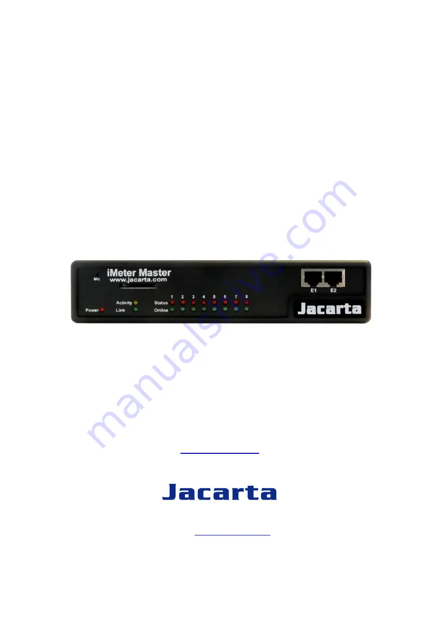
background image


iMeter Master 

Ethernet Power & Environmental Monitoring System


USER MANUAL 


v1.2 


www.jacarta.com 


T. +44 (0) 1672 511125 

Email

[email protected]


Summary of Contents for iMeter Master

Page 1: ...iMeter Master Ethernet Power Environmental Monitoring System USER MANUAL v1 2 www jacarta com T 44 0 1672 511125 Email support jacarta com ...

Page 2: ...iMeter ...

Page 3: ...atibility Generic immunity standard Part1 Residential and light industry RoHS This device is RoHS compliant WEEE In accordance with the European Directive 2002 96 EC on Waste Electrical and Electronic Equipment WEEE Jacarta will arrange for the appropriate disposal of the product upon return of the product at the end of its serviceable life Safety Information To reduce the risk of fire or electric...

Page 4: ...t and rear panels 7 2 Installation 8 2 1 Setting the IP address 8 2 2 Testing the IP address 8 2 3 Firmware upgrade 10 2 4 Setting up a sensor 18 2 5 Expansion ports 19 3 Notifications 26 3 1 Adding a notification 26 3 2 SNMP Trap 27 3 3 Email 30 3 4 SMS 30 4 Mapping 35 4 1 Adding a map 35 4 2 Monitoring via map interface 37 5 Filters 39 5 1 Sensor filters 39 5 2 Syslog filters 39 6 FAQ 43 ...

Page 5: ...specific set ups and answers some commonly asked questions If you need any further information or help with using your unit then please contact us and one of our technical support staff will be only too pleased to help you with any information you require 1 3 Package Contents The iMeter Master package contains the following items 1x Product CD 1x 5ft Crossover cable 1x 7 5 3A power supply 2x Brack...

Page 6: ...mware upgrade has been incomplete This will be indicated by the unit displaying a continuously lit row of red LEDs If this happens please contact us on support jacarta com 4 Mic The mic is a small hole for access to the internal microphone This can be used as a sound sensor or an external mic can be used 5 Expansion Ports There are four expansion ports numbered from E1 E4 These are expansion ports...

Page 7: ...icrophone for voice modem applications 6 Audio in out The in is used to connect an external microphone the output for external speakers 7 RS485 Port Used for Modbus connectivity The iMeter supports Modbus master or slave 8 Power Connector This is a 7 5V DC plug We recommend you using a 7 0 9 V 3A power supply 9 Ethernet Port This RJ45 port is used to connect the iMeter to the network ...

Page 8: ...arting RJ45 CAT5 crossover cable with RJ45 male connection A PC with Ethernet card or LAN socket Power socket for the unit to connect to a Connect the unit via the Ethernet port of the unit to the computers LAN or Ethernet port with a CAT5 crossover cable b Set a static TCP IP details on the computer of o IP address 192 168 0 1 o Subnet Mask 255 255 255 0 o Default Gateway 192 168 0 1 c Open a web...

Page 9: ...etwork from the list on the left frame of the page Don t forget to set the subnet mask default gateway and domain name server if DHCP is not used The unit ships with DHCP disabled If DHCP is required to obtain the IP address then select Yes against the Use DHCP option and click Save ...

Page 10: ...ress Once this is done use the ping command to test the unit This can also be used as a diagnostic tool in order to check whether your unit is connected to the network After hitting enter you will get an MS DOS prompt window that will show the test results as below If unsuccessful you will get a message saying request timed out This indicates either an incorrect IP address or a unit that is not co...

Page 11: ...ed please contact us at support jacarta co uk a b c This pop up will appear on screen This tutorial provides you the information needed to upgrade the firmware To get to the starting point of this tutorial Log in as administrator Click on the settings tab ...

Page 12: ...ime so please be patient The page will display the following message while rebooting e Once the unit has rebooted the following page will be displayed Follow these instructions f During the process the following message will be displayed The unit will then reboot The process is complete when the LED s are back to their normal status ...

Page 13: ...e port 1 b Auto detection Now point a browser to the IP address of the unit default 192 168 0 100 The summary page will be displayed first The temperature sensor should be auto detected and listed along with its current reading and status If this is not shown please see refer to the FAQ This summary page allows you to quickly see which sensors are connected their status and view the system log We ...

Page 14: ...or is indicating a temperature of 35 degrees C and a status of High Warning If you click on the blue marker arrow indicated above by the Set the required threshold label you can drag this marker to re configure the thresholds After dragging the marker click save The next screen shot shows that this marker has been moved to make a new threshold and along with it the sensor status has changed If the...

Page 15: ...be taken offline then click on the sensor currently button This will offline the sensor without the need for it to be physically unplugged Now the page will look something like below after taking the sensor offline To bring a sensor back online select your sensor type from the drop down menu and click save ...

Page 16: ...o 2 then the sensor would have to drop from 30 down to 27 before the status would change from Warning High back to normal Reading offset A calibration tool If the temperature sensor needs to be calibrated for example an offset value of 5 could be entered This would mean if the sensor reads 20 degrees then it would record as 25 degrees This figure can also be a minus figure e g 5 would show 15 degr...

Page 17: ...e An airflow sensor or water detector may have temporary drops in readings which are normal operating characteristics a logical counter measure to prevent unwanted alarms would be to set a time limit to show abnormal conditions Enable Calendar If you select this option then the following will be displayed As an example an office building is to be monitored between the hours of 7 PM 9 AM Monday Fri...

Page 18: ... you require information on specific functions of a particular sensor or expansion board then please contact us on support jacarta com a Plug the expansion board into one of the four ports located on the front panel of the unit These are numbered E1 E4 b From the summary page navigate to the Sensors tab Then click Expansion Modules as outlined in the image below c A list of all expansion ports wil...

Page 19: ...ons define the action to take when the sensor gives a reading beyond the set thresholds This section discusses how to setup a notification when a sensors reading has reached the specified parameters high warning critical etc that were covered in the previous section This tutorial provides you the information needed to setup a notification To get to the starting point of this tutorial Login as admi...

Page 20: ...cation step by step 3 2 SNMP Trap First we will set up a notification via SNMP trap so that when the sensor reaches a certain threshold it will send a notification to an SNMP server This tutorial provides the information needed to setup an SNMP trap To get to the starting point of this tutorial Log in as administrator Click the Notifications tab Choose Notifications wizard Choose SNMP trap ...

Page 21: ...ination button After clicking this you have the option of inputting another trap or clicking on Next Now you can enter the following parameters These parameters set the maximum number of times to send the trap notification and the time interval between each notification c After clicking next the following selection screens will be displayed ...

Page 22: ...e temperature sensor we have connected on port 1 The trap will be sent when the sensor reads a High Critical and named this bind SNMP Trap 1 d Once we have created the parameters for the SNMP trap we need to make it active To do this go back to the notifications tab and it should look like the following e Select the sensor and SNMP trap parameters as before ...

Page 23: ... has been added to our notifications page Note To remove this trap and make it inactive highlight the notification and click remove You can repeat this process to set up multiple SNMP traps for different sensors or for multiple SNMP servers ...

Page 24: ...n be added The Customize button will re write the fields in a format that will allow for an automated e mail to display the sensor information After this click Next This tutorial provides you the information needed to setup an E Mail Notification To get to the starting point of this tutorial Log in as administrator Select the Notifications tab Click Notification Wizard ...

Page 25: ...elevant information has been added click next d Now as with the SNMP trap the number of times to resend can be selected and the time to elapse between each attempt Click next when the parameters are filled in e Now link the e mail we just created to the temperature sensor on port 1 ...

Page 26: ...iMeter Click on Finish to be taken back to the main Notification tab f Click on create g Create the notification link as before Then click finish ...

Page 27: ...Warning 3 4 SMS Now we will set up a notification so that an SMS message will be sent This message can be sent via a GSM GPRS mobile phone connected via a Bluetooth connection or the USB port a From the list of notification types select SMS and click next This tutorial provides you the information needed to setup a SMS notification To get to the starting point of this tutorial Log in as administra...

Page 28: ...iMeter b Now either add multiple numbers or click next In our case we will click next c Now we will set up the message that will be sent to the phone on the following screen ...

Page 29: ...r notifications d Once the Customized button is pressed the SMS message changes its format to include the Macro script e Next we will choose to set up the type of connection This will depend on the type of modem you are connecting For the purpose of this tutorial we will assume you are connecting a GSM GPRS enabled modem to the serial port Therefore we will select COM1 from the list f Now select t...

Page 30: ... This time we will use this notification for a low warning Then select the notification name we assigned in this case we chose SMS 1 Click Finish to finalize this h Now we will add the SMS notification to our active list This is the same process as for the others simply click on create and then select the appropriate parameters ...

Page 31: ...iMeter i Back at the main notification page the page should display three types of notifications the SNMP trap E mail and SMS ...

Page 32: ... for an instant visual feedback as to a sensors position and status It is a useful monitoring tool for a set up with several sensors in different positions 4 1 Adding a map a First we need to add a picture file to be used as the map This can be a blueprint of your office a 3D picture of your office site being monitored or a photo of the wiring closet you are monitoring b Now you can browse to the ...

Page 33: ... a campus site d Choose to have the map as a top level map e There is now the option to finish or to continue adding sensors to the map For this tutorial click next f The map page will be displayed along with the map To continue adding the sensors click next ...

Page 34: ...will be directed to click the Unlock button h Sensor icons can now be dragged on to the map and positioned i After the sensors are in the correct position on the map click on Lock and then click on the Finish button to save the changes ...

Page 35: ...tatus and use the map interface a To see further information regarding a sensor you can click on its icon First you must click on the Lock Icons button If other sensors are connected these too can be dragged and positioned on the map b Click on Show Graph to view a graph of the sensors collected data ...

Page 36: ...tion which is displayed within the summary page To enter the filter menu select Sensor Filters from the dropdown tab on the left of the page b Once you have clicked the tab you will be able to select the desired filter results by altering various fields of information contained within the sensor filter window ...

Page 37: ...ll be displayed in the Sensor Information window found on the summary page 5 2 Syslog filters a Syslog filters enable customization of the syslog window To begin select the Syslog filter tab found on the summary page b Once selected the tab will allow selection of desired filter results by altering various fields of information contained within syslog filter window ...

Page 38: ...reaload interval can be achieved by using the options shown below e Once you have selected the desired filter options the new settings will be displayed in the Sensor Information window found on the summary page 6 FAQ a I can not see the temperature sensor displayed on summary page b I can not access my units web based interface c What do my LED lights mean ...

Page 39: ... for the temperature sensor If this is not checked it should be then it will be displayed in the list of connected sensors b I can not access my units web interface If you re having issues with network connectivity first ensure that the link LED is lit on the front display of the unit If this is not lit then you have no network connection present If this is the case then ensure the following If co...

Page 40: ...iMeter LED patterns in Normal mode then LED patterns in Safe mode ...

Page 41: ...iMeter then ...

Page 42: ...rocess After the root file system is mounted all green LEDs will be flashing and red LEDs light increasingly from left to right The onboard web server can be accessed during this time and shows a splash screen with boot details After the boot process is finished the LEDs show the status of the online sensors d I have forgotten my units IP address You can use IPSET to search for the IP address or p...

Page 43: ...n I change my administrator password If you wish to make your unit more secure and change the administrator password from the default public to your own choice follow these steps Log into your unit using the default password Point towards the settings tab Change the password h What function do the different types of notifications provide The notifications are used to notify you when a sensor readi...

Page 44: ...This will send a signal to wake or shut down a server i What is the Heartbeat message This setting is to have the iMeter notify you it is still running You can be notified by either traps or by e mail Alive Trap settings Send Keep Alive Traps Default Off Select on if you want the system to send Alive Traps Destination enter the IP address of the server to send traps to ...

Reviews: