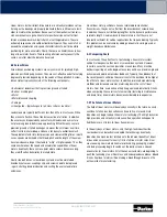
www.parkermotion.com
Parker Hannifi n Corporation
Electromechanical Automation Division
4
2.2 Ironless Motors
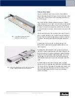
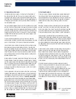
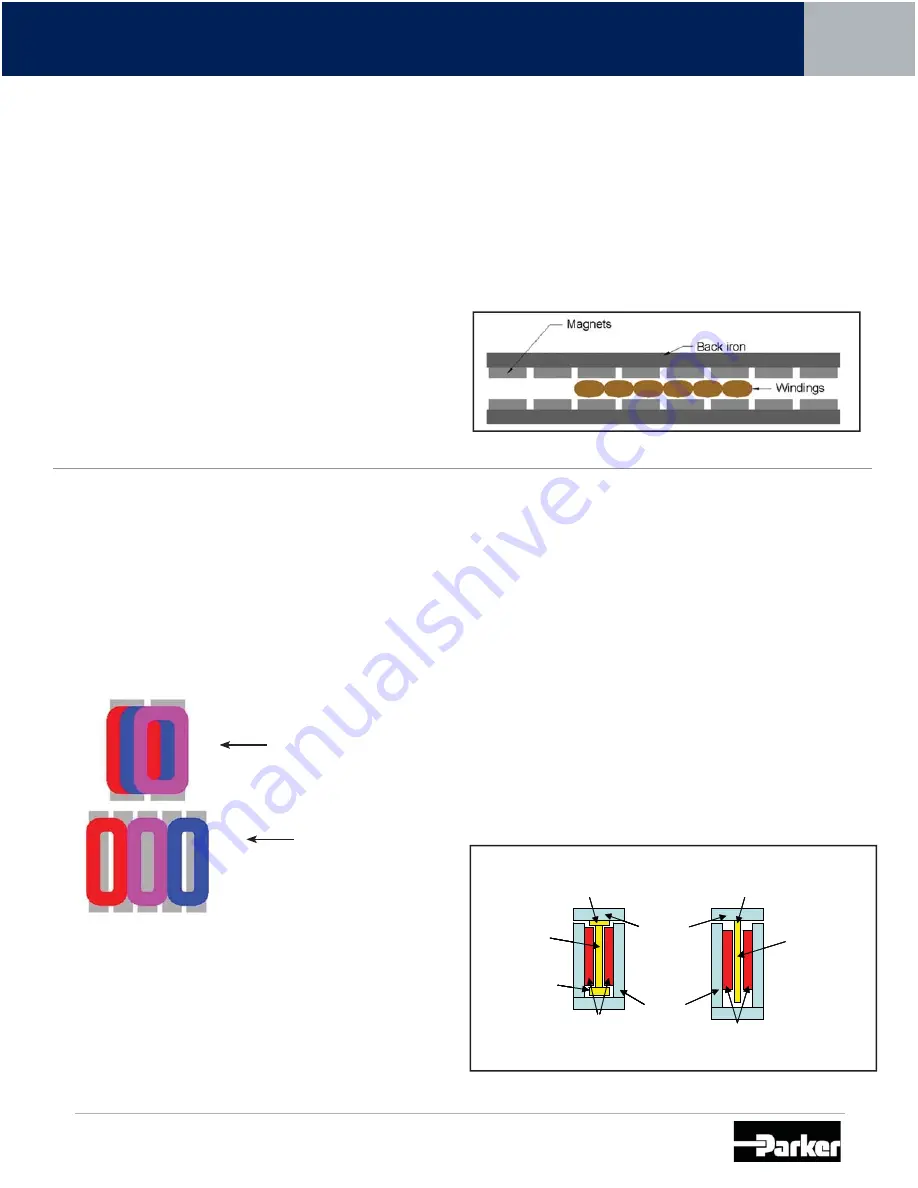
Ironless motors consist of a forcer which rides between dual magnet rails
(Fig. 8). They are also known as “aircore” or “U-channel” motors. The
forcer does not have any iron laminations in the coil – hence the name
ironless. Instead, the copper windings are encapsulated and located in
the air gap between the two rows of magnets. Because the motors are
ironless, there are no attractive forces or cogging forces between the
forcer and the magnet track.
In addition, the forcers have lower mass than their ironcore counterparts.
What results is a motor design that allows for extremely high accelerations
and overall dynamic performance. The ironless design has zero cogging
and the lack of attractive force allows for extended bearing life and, in
some applications, the ability to use smaller bearings.
While the high dynamic performance and zero cogging motion make the
ironless motors a powerful design, they are not as thermally effi cient
as their ironcore counterparts. A small contacting surface area and a
long thermal path from the winding base to the cooling plate makes the
full-load power of these motors low. In addition, the dual row of magnets
increases the overall cost of these motors in relation to the generated force
and stroke length.
Fig. 8: Ironless Linear Motor
Parker Trilogy’s patented I-beam shape and overlapping winding design
provides very high forces in a compact package. In addition, the design
is more thermally effi cient than tradition ironless motor designs.
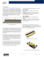
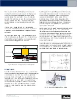
By overlapping the windings (Fig. 9) instead of arranging them side-by-
side, Parker Trilogy is able to provide a motor with a very high power
density. The result is a package size considerably smaller than competitive
motors with similar force capabilities.
Overlapping windings for
shorter overall length
Non-overlapped windings
result in longer package length
Fig. 9: Overlapping Windings
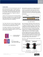
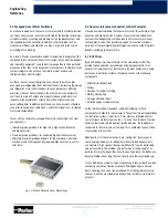
Parker Trilogy creates the I-beam shape by fl aring out the end turns of
the motor at a 90-degree angle. The end turns of a linear motor coil do
not contribute to the horizontal force component of the motor. Instead
of producing force, the end turns simply produce heat. Parker’s I-beam
shaped design allows for better heat transfer between the motor coils
and the heat sink by increasing the contacting surface area between
components (Fig. 10). The combination of overlapped windings and the
I-Beam shape creates a more thermally effi cient motor than most
traditional ironless motors. As a result, the payload will experience
less thermal expansion due to heat from the motor. In high precision
applications, thermal expansion can adversely affect the overall system
accuracy. Parker Trilogy motors will help maintain system accuracy by
running at lower operating temperatures than our competitors. In addition,
there are added benefi ts of the I-beam shape by lowering the overall
profi le height and creating a stiffer mechanical structure.
What results is a compact motor design with high force and extraordinary
thermal characteristics.
Fig. 10: Parker Trilogy’s Patented I-Beam Design
Good surface area for
efficient heat transfer
Dual rows of magnets
Dual rows of magnets
Vacuum encapsulated
inronless coil with
I-beam shape
I-beam shaped coil for
lowerprofile, better
thermalefficiency and
higher structural stiffness
U-Shaped
magnet track
Non I-beam (T shaped)
coil with larger profile size,
less thermal efficiency
and less rigidity
acts as heat sink/
adapater plate
Small surface area for
poor heat transfer
Trilogy I-beam design
Competitive designs


