www.parkermotion.com
Parker Hannifi n Corporation
Electromechanical Automation Division
7
Engineering
Reference
4.1 Commutation of the motor
In traditional rotary servo systems, it is important for the amplifi er to
know the position of the rotor. This way it can properly switch current
through the motor phases in order to achieve the desired rotation of the
shaft. Many times, three digital Hall effect sensors (spaced 60 degrees or
120 degrees apart) are used in order to provide positional information of
the shaft within 6 states.
The same principle applies to linear motors. The amplifi er must know the
position of the forcer in relationship to the magnet rail in order to properly
switch the windings. Rather than aligning the Hall effect devices (HEDs)
within one complete revolution of the shaft, the Halls are matched to the
magnetic pole pitch of the motor. The “pole pitch” is the linear distance
traveled within one electrical cycle of the motor and is analogous to one
revolution of a rotary motor.
Once the amplifi er establishes the position of the forcer within the
electrical cycle, it will then switch the motor phases whenever a transition
occurs in the Hall states. This is known as
trapezoidal commutation.
In most modern servo amplifi ers, the position of the forcer need only be
determined upon power up and enabling of the drive. Once the initial
position is recognized, the drive can commutate off of the position sensor,
which provides signifi cantly higher resolution feedback than the digital
HEDs. This allows the motor to be sinusoidally commutated. Sinusoidal
commutation provides a smoother switching sequence resulting in less
disturbances and less heat.
Another method of sinusoidal commutation is through the use of analog
Hall effect devices. Analog Halls produce a sinusoidal signal as they pass
over the magnetic poles of the magnet track. Analog Halls have also been
used as an inexpensive method of providing positional feedback as well
as commutation feedback. However, these devices are susceptible to
picking up noise which can affect commutation – which in turn, affects
smoothness of travel.
In some applications, HEDs are not desired – either from a cost savings
standpoint, reduced wiring / component count, or other application spe-
cifi c standpoint. However, the servo drive must still be able to recognize
the position of the motor forcer. In this case,
automatic commutation
can be achieved with a properly equipped servo drive.
Parker’s Com-
pax3
drive/control has an “auto-commutation with test movement” func-
tion that automatically establishes the commutation angle. In this system,
the Compax3 applies a test signal which induces small movements in the
motor upon power up. The physical size of these movements can be quite
small – as small as 10 electrical degrees (less than 2 mm on many linear
motors), so there is no need to worry about the motor “
jumping.
” In addi-
tion, the test signals are “softened” such that system jerk is minimized.
4.2 Positional Feedback
There are a variety of methods to provide linear positional feedback to
the motion controller. There are analog transducers, rack-and-pinion
style potentiometers, and laser interferometers, to name a few. Each has
its own level of accuracy and cost. But far and away the most popular
feedback device for linear motor positioning systems is the linear
encoder.
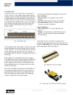
Most linear encoders provide an incremental pulse train that provides
discrete “counts” back to the motion controller as the encoder “read
head” moves along a “linear scale.” Typically, the read head is mounted
close to the load and the linear scale is applied to the positioner base.
There are two popular styles of linear encoders – optical and magnetic.
Optical encoders use refl ected light scanning techniques to provide
feedback with extremely high resolution and accuracy. Optical encoders
are capable of providing feedback in the nanometer resolutions. Magnetic
encoders use inductive scanning techniques to offer signifi cantly more
economical feedback, but have considerably lower accuracy and resolu-
tion. Magnetic encoders can typically offer resolutions down between the
1 to 5 micron range.
A third variation of linear encoder is the Sine encoder. The Sine encoder
produces analog sine and cosine signals instead of discrete pulses.
Many modern motion controllers have the ability to interpolate these
analog signals into extremely fi ne resolutions. For example, the Compax3
controller can interpolate a 1 Vpp signal into 14 bits, i.e., the sine/cosine
signal period is divided into 16,384 counts. A typical pitch period of a Sine
encoder is 1mm, thus the resolution can be interpolated down to 62 nm
in the controller.
All of these encoders provide incremental positioning information.
Hence, it is necessary to establish a
home position
any time positional
information is lost by the controller, i.e., power down. In some
applications it is necessary to have
absolute feedback
where the actual
position of the motor is known immediately and no homing sequence
is required. Some encoder manufacturers are now making absolute
linear encoders that transfer data using a synchronous serial interface
(SSI). Parker’s
Aries
family of servo drives support absolute feedback
transmitted via SSI. Please contact your Parker representative for further
details.
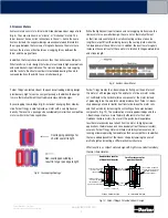
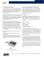
Fig. 17: Parker ACR Controller
and Aries Drives


