10
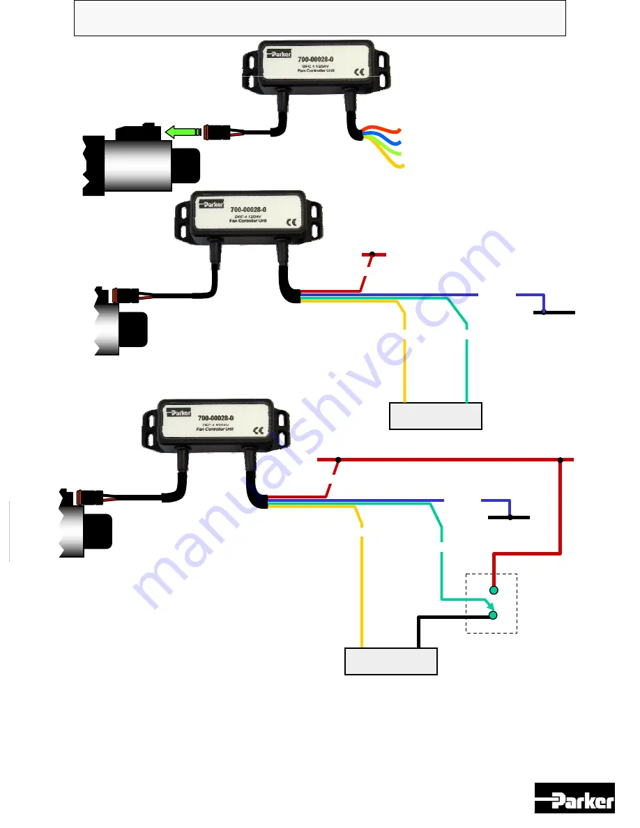
700-00028-0, DFC-4 Fan Driver Unit.
NOTE:-
The ‘Emergency Fan
MINIMUM SPEED’ configuration
shown above assumes that the
controller is being used with an
inverting operation pressure valve
and the PWM input is positive logic
i.e. :
0% PWM = fan full on, 100%PWM =
fan full off.
Red
Blue
Yellow
Green
+10 to +32V supply I/P
0V Supply I/P
PWM 0V I/P
PWM Signal I/P
Proportional
valve
0VDC
+10 to +32V max supply input
+ PWM
output
Engine Control Unit
( ECU )
PWM 0V
output
1
2
1
2
0VDC
+10 to +32V max supply input
+ PWM
output
PWM 0V
output
Emergency Fan
MINIMUM
SPEED
relay
configuration.
NC
NO
1
2
Closing the relay will force the input to 24V supply voltage and the fan will be controlled to
fully OFF ( the fan may still rotate even in this state, if absolute zero fan speed is required, an
additional external valve will be needed ) and will remain in this state until the relay is released.
If the Inverted mode is selected, the relay should be connected to 0V to achieve fan MINIMUM
SPEED when relay energized.
Connection Guide: -
Proportional
valve
Proportional
valve
RED
GREEN
YELLOW
BLUE
Engine Control Unit
( ECU )
RED
BLUE
YELLOW
GREEN
External relay
( supplied by others )


