background image

A. Connectors and Pin Assignments

A-4


October 

2002

4200-A2-GN20-10

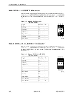
Model 4210 ALARM/BITS Connector

The alarm relay reports major alarms through the ALARM connector (top row of 
contacts on the ALARM/BITS terminal block) on the front panel of the GranDSLAM 
Model 4210. The BITS connector (bottom row of contacts, pins 1–3) is for future 
use.   

Models 4220/4230 ALARM/BITS Connector

The alarm relay reports major alarms through the ALARM connector (top row of 
contacts on the ALARM/BITS terminal block) on the front panel of the GranDSLAM 
Models 4220 and 4230.  The BITS connector (bottom row of contacts, pins 1–5) is 
for future use.

Table A-4.

Model 4210 ALARM/BITS 
Connector Pinouts

Signal

Direction

Pin

BITS Tip

In

1

BITS Ring

In

2

BITS Shield

Ground

3

Major Alarm

Out

4

Common

Out

5

Minor Alarm

Out

6

02-17340

3    2    1

6    5    4

Table A-5.

Models 4220/4230 ALARM/BITS 
Connector Pinouts

Signal

Direction

Pin

BITS Tip

In

1

BITS Ring

In

2

BITS Shield

Ground

3

4

5

Major Alarm

Out

6

Common

Out

7

Minor Alarm

Out

8

Alarm Sense +

In

9

Alarm Sense –

In

10

02-17341

5 4 3 2 1

10 9 8 7 6

Содержание GranDSLAM 4200

Страница 1: ...GranDSLAM 4200 ATM Stackable DSLAM Installation Guide Document No 4200 A2 GN20 10 October 2002...

Страница 2: ...service representative or distributor directly for any help needed For additional information concerning warranty sales service repair installation documentation training distributor locations or Para...

Страница 3: ...VDC 20A single pole circuit breaker or switch must be included in the ungrounded supply conductor Over current protection must be included with a 20A 48 VDC fuse or circuit breaker in the ungrounded c...

Страница 4: ...ly to cause harmful interference in which case the user will be required to correct the interference at his own expense The authority to operate this equipment is conditioned by the requirements that...

Страница 5: ...ct based on the standard of the Voluntary Control Council for interference by Information Technology Equipment VCCI If this equipment is used in a domestic environment radio disturbance may arise When...

Страница 6: ...E October 2002 4200 A2 GN20 10...

Страница 7: ...ts for Rack Mounting 1 6 Installing the GranDSLAM 4200 Into a Rack 1 8 Installing the GranDSLAM 4200 on a Wall 1 10 Installing the GranDSLAM 4200 on a Shelf or Desktop 1 12 Installing the Uplink Modul...

Страница 8: ...4 Configuring the Unit for Operation 4 5 A Connectors and Pin Assignments Overview A 1 DSL Ports and POTS Splitter Connectors A 2 Management Port Connector A 3 Console Port Connector A 3 Model 4210 AL...

Страница 9: ...ians who install the GranDSLAM 4200 ATM Stackable DSLAM New Features for This Release This version of the document supports GranDSLAM Release 2 0 and adds the following information Model 4220 ADSL uni...

Страница 10: ...g and usage of the front panel LEDs Chapter 4 Configuration Describes the minimal configuration steps required to prepare the GranDSLAM 4200 for remote access Appendix A Connectors and Pin Assignments...

Страница 11: ...a a Transaction Language No 1 TL1 Command Line Interface CLI or the unit may be managed using a network management system such as the Paradyne GrandVIEW Element Management System EMS Up to five GranDS...

Страница 12: ...a wall The standard mounting brackets provided can be fastened to the base of the unit for wall mounting Set on a shelf or desktop Up to five GranDSLAM 4200 units may be stacked on a shelf or desktop...

Страница 13: ...0 to an upstream ATM network A GranDSLAM 4200 aggregation unit to a basic unit in a stack MGMT 8 position modular plug and 8 wire Category 5 or better unshielded twisted pair UTP cable The GranDSLAM 4...

Страница 14: ...arefully remove the unit from its shipping container and check for physical damage If the unit shows signs of shipping damage notify your sales representative Package Contents In addition to this inst...

Страница 15: ...24 x 1 2 for use with self retaining nuts 5 Machine screw with captive starwasher 10 32 x 1 2 for use with racks with threaded holes 5 Captive pan head screw for replacing long Telco screw 3 Rubber fo...

Страница 16: ...d with Paradyne Part Number 868 6282 0020 are shipped with the unit Two brackets suitable for a 21 inch 535 mm rack marked ETSI are available from Paradyne as a separate feature see Appendix B Equipme...

Страница 17: ...chine screws for 23 inch racks provided with the mounting brackets in the hardware kit 4 Attach the brackets appropriate to your rack size Tighten all screws firmly 02 17324 23 inch 584 mm EIA and Bay...

Страница 18: ...attach the unit to a ground while you have unrestricted access to the grounding lug on the side of the unit See Grounding Lug in Chapter 2 Cabling for more information Procedure To install the GranDS...

Страница 19: ...Uplink Module on page 1 13 23 inch 584 mm Nortel Rack Mount 1 12 13 24 DSL PORTS 1 24 POTS 1 24 4 8 16 20 POWER A ALARM RTN 48VDC BITS MGMT CONSOLE STATUS UPLINK ALRM TEST B A 3 5 A 60 B E1 MODULE 420...

Страница 20: ...To install the GranDSLAM 4200 on a wall 1 Identify the flat head screws provided in the hardware kit and the brackets suitable for a 19 inch rack Two screws are required for each bracket 2 Orient the...

Страница 21: ...s Leave them so their heads are about 1 4 inch 6 mm from the wall 7 Hang the unit from the wood screws to verify that the screws are properly placed The screws should freely slide into the top of the...

Страница 22: ...s stamped into the bottom of the unit show the proper positions for the feet 3 Remove the protective sheet from the bottom of each foot then press the foot onto a corner of the bottom of the unit 4 Tu...

Страница 23: ...attempting to operate it HANDLING PRECAUTIONS FOR STATIC SENSITIVE DEVICES This product is designed to protect sensitive components from damage due to electrostatic discharge ESD during normal operat...

Страница 24: ...il it is fully seated and the faceplate of the uplink module is flush against the faceplate of the GranDSLAM 4200 4 Fasten the two screws provided with the uplink module Do not plug in the unit Procee...

Страница 25: ...r describes all possible connections not all of which are required DSL Ports on page 2 2 4201 T1 Uplink Module Connector on page 2 3 4202 E1 Uplink Module Connectors on page 2 4 4203 T1 E1 IMA Uplink...

Страница 26: ...screw attach the cable to the DSL PORTS 1 24 connector and fasten it to the jack screw with its short captive screw 3 If the connector for your cable has a long captive screw remove the provided jack...

Страница 27: ...d 8 you must first obtain a cable with a shielded plug and connect the cable shields drain wires to the plug s shield If your cable has separate shields for transmit and receive you must ground both d...

Страница 28: ...eld to pins 7 and 8 then the cable s shield will not be grounded at the module end To ground the cable shield at the module end you must use a cable with a shielded plug and the cable shields drain wi...

Страница 29: ...fault to 75 using the ENT T1 or ED T1 TL1 command LINETYPE G703SHORT75 3 Plug the TX coaxial cable into the TX 75 jack 4 Plug the RX coaxial cable into the TX 75 jack CAUTION Do not plug cables into b...

Страница 30: ...ds for transmit and receive you must ground both drain wires You can also ground the shields at the far end or you can use a nonshielded cable Procedure To connect to the 4203 T1 E1 IMA Uplink Module...

Страница 31: ...IMA Module 02 17333 T1 E1 MODULE 4203 1 2 3 4 5 6 7 8 1 12 13 24 4 8 16 20 POWER A ALARM RTN 48VDC BITS MGMT CONSOLE STATUS UPLINK ALRM TEST B A 3 5 A 60 B E1 MODULE 4202 TX RX 120W 75W 1 12 13 24 4 8...

Страница 32: ...Procedure To install the ferrite choke onto the DSL cable s 1 Open the ferrite choke and place it around the cable s as close to the cable connector on the uplink module as possible 2 Close the two h...

Страница 33: ...A straight through cable is used Procedure To use the MGMT port 1 Connect a modular 8 pin cable to the MGMT port 2 If the GranDSLAM 4200 is in a rack fasten the cable to a rail with a cable tie 3 Con...

Страница 34: ...on program to use the following parameters Maximum speed 9600 bps Data bits 8 Parity None Flow Control None Stop bits 1 2 Determine and procure the proper Data Terminal Equipment DTE cable type The CO...

Страница 35: ...r to the CONSOLE port socket 3 If the modem will be permanently connected fasten the connector to the Management Module with its captive screws If the GranDSLAM 4200 is in a rack dress the cable to th...

Страница 36: ...hysical alarms The other two contacts provide access to a sense circuit that can be used to detect the open or closed condition of an external alarm relay See Figure 2 1 Alarm Connection Example for a...

Страница 37: ...above it For Models 4220 4230 use a screwdriver to press the orange spring tab in while inserting the wire into the hole below it NOTE For all models the insulation should be fully within the plug and...

Страница 38: ...4200 02 17280 CO Alarm Monitoring System 1 12 13 24 4 8 16 20 POWER A ALARM RTN 48VDC BITS MGMT CONSOLE STATUS UPLINK ALRM TEST B A 3 5 A 60 B E1 MODULE 4202 TX RX 120W 75W Model 4210 02 17329 CO Alar...

Страница 39: ...ocated on the side panel near the front of the unit 3 Insert the stripped end of the wire through the bottom of the grounding lug and tighten the screw Ensure that the screw makes contact with the str...

Страница 40: ...ot powered that is the circuit breakers or fuses are open at the source Procedure To supply 48 VDC power to the GranDSLAM 4200 from a single 48 VDC power source 1 Strip the tips of the power source wi...

Страница 41: ...left and fasten them to the rail with a cable tie 5 Power on the GranDSLAM 4200 6 Make sure the STATUS LED on the front panel is ON green See Chapter 3 LEDs Insert the Into the Negative side of the po...

Страница 42: ...2 Cabling 2 18 October 2002 4200 A2 GN20 10...

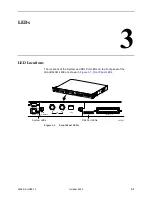
Страница 43: ...n Figure 3 1 Front Panel LEDs Figure 3 1 Front Panel LEDs 1 12 13 24 DSL PORTS 1 24 POTS 1 24 4 8 16 20 POWE R A ALARM RTN 48VDC BITS MGMT CONS OLE STATUS UPLINK ALRM TEST B A 3 5 A 60 B E1 MODU LE 42...

Страница 44: ...en Off On Blinking The port is disabled or no signal is detected on the line The port has successfully trained with the remote and is active The port is attempting to train STATUS Green Off On Blinkin...

Страница 45: ...GranDSLAM 4200 Inband management managing via a PVC from the NOC Managing out of band through the Ethernet port Additional configuration is also necessary if you do not choose to accept the defaults...

Страница 46: ...ompletion of optional fields Pressing the Tab key while entering a command causes the CLI to fill in the optional fields For example enter RTRV HDR Press the Tab key the CLI fills in the TID RTRV HDR...

Страница 47: ...of TL1 commands or an NMS system such as Paradyne s GrandVIEW Element Management System EMS you configure the unit for operation The turn up procedure for the GranDSLAM 4200 system differs depending...

Страница 48: ...strings the SYSLOG server and trap managers 4 Change the time if necessary The Simple Network Time Protocol SNTP which maintains the unit s clock defaults to enabled However you can change the time o...

Страница 49: ...command See the GranDSLAM 4200 ATM Stackable DSLAM User s Guide for more information Configuring the Unit for Operation Once the unit is connected to the network the following turn up procedures shoul...

Страница 50: ...4 Configuration 4 6 October 2002 4200 A2 GN20 10...

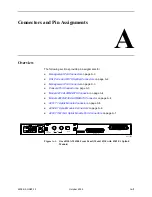
Страница 51: ...3 Model 4210 ALARM BITS Connector on page A 4 Models 4220 4230 ALARM BITS Connector on page A 4 4201 T1 Uplink Module Connector on page A 5 4202 E1 Uplink Module Connectors on page A 6 4203 T1 E1 IMA...

Страница 52: ...gnation for this connector is CA21A The connector is labeled POTS 1 24 Table A 1 lists the pin assignments for each of these interfaces Note that Pins 25 and 50 are not used Table A 1 DSL Connector Pi...

Страница 53: ...DB9 socket connector that supports an EIA 232 circuit as shown in Table A 3 Table A 2 Management Port Pinouts Signal Pin Transmitted Data 1 Transmitted Data 2 Received Data 3 Unused 4 Unused 5 Receiv...

Страница 54: ...connector top row of contacts on the ALARM BITS terminal block on the front panel of the GranDSLAM Models 4220 and 4230 The BITS connector bottom row of contacts pins 1 5 is for future use Table A 4 M...

Страница 55: ...ctor is a single RJ48C unkeyed shielded 8 pin modular jack The shield is connected to ground via the module Pin assignments for the 100 connector are shown in Table A 6 Table A 6 4201 T1 Uplink Module...

Страница 56: ...s each use coaxial cables that are unbalanced with respect to ground The shield of the TX cable is connected directly to ground at the E1 module The shield of the RX cable is capacitor coupled to grou...

Страница 57: ...ht RJ48C unkeyed shielded 8 pin modular jacks The shield is connected to ground via the module Pin assignments for the T1 100 impedance E1 120 impedance port connectors 1 8 are shown in Table A 9 Tabl...

Страница 58: ...A Connectors and Pin Assignments A 8 October 2002 4200 A2 GN20 10...

Страница 59: ...rackets and hardware and Installation Guide 4211 A1 530 GranDSLAM 4200 24 Port ReachDSL with 4201 T1 Uplink Module with POTS Splitter with Japan defaults Includes GranDSLAM 4200 19 and 23 inch mountin...

Страница 60: ...with Japan defaults Includes GranDSLAM 4200 19 and 23 inch mounting brackets and hardware and Installation Guide 4213 A1 533 GranDSLAM 4200 24 Port ADSL without Uplink Module without POTS Splitter wit...

Страница 61: ...23 inch mounting brackets and hardware and Installation Guide 4221 A1 533 GranDSLAM 4200 24 Port ADSL with 4202 E1 Uplink Module without POTS Splitter with EMEA defaults Includes GranDSLAM 4200 19 and...

Страница 62: ...MEA defaults Includes GranDSLAM 4200 19 and 23 inch mounting brackets and hardware and Installation Guide 4230 A1 522 GranDSLAM 4200 24 Port ADSL with 4202 E1 Uplink Module without ISDN Splitter with...

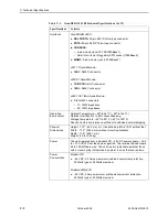
Страница 63: ...DSLAM 4200 is independently cooled with integral fans and does not rely on vertical air flow Electromagnetic Compatibility EMC Meets the following standards CISPR 22 Class A EN 300 386 2 EN 55024 EN 5...

Страница 64: ...0 to 185 F Shock and vibration tolerance sufficient to withstand normal shipping Physical Dimensions Height 1 75 44 5 mm or 1U as defined in EIA 310 C without feet Width 17 2 436 9 mm without mounting...

Страница 65: ...Uplink Module A 6 front panel A 1 Management port A 3 POTS splitter A 2 T1 Uplink Module A 5 T1 E1 IMA Uplink Module A 7 CONSOLE port cabling and settings 2 10 connector A 3 description 1 3 pin assign...

Страница 66: ...al 4 3 mounting brackets description 1 6 mounting configurations 1 6 O operating environment C 2 optional mounting brackets 1 6 order numbers B 1 overview 1 1 configuration 4 1 of book iv P package co...

Страница 67: ...ts A 7 RJ48C connectors A 7 technical specifications C 1 Telco connectors fastening 2 2 terminal cabling and settings 2 10 TL1 commands 4 2 troubleshooting LEDs 3 1 typographic conventions 4 1 U unpac...

Страница 68: ...Index IN 4 October 2002 4200 A2 GN20 10...

Отзывы: