2. Cabling
4200-A2-GN20-10
October 2002
2-13
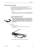
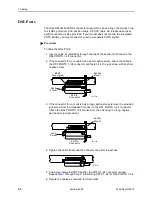
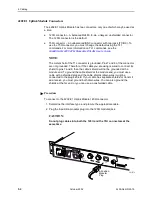
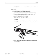
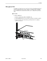
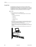
Procedure
To connect the ALARM interface:
1. Strip the tips of the alarm source wires (about 1/2 inch or 12.7 mm in length).
2. For Model 4210, insert the wires into the 3-position plug. Securely fasten each
wire by tightening the screw above it.
For Models 4220/4230, use a screwdriver to press the orange spring tab in
while inserting the wire into the hole below it.
NOTE:
For all models, the insulation should be fully within the plug and no bare
wire should be exposed outside of the plug.
3. Insert the plug into the ALARM interface on the front panel of the
GranDSLAM 4200.
4. If the GranDSLAM 4200 is in a rack, dress the cable to the left and secure it to
the rail with a cable tie.
02-17283
02-17328
Spring
Tab
Содержание GranDSLAM 4200
Страница 1: ...GranDSLAM 4200 ATM Stackable DSLAM Installation Guide Document No 4200 A2 GN20 10 October 2002...
Страница 6: ...E October 2002 4200 A2 GN20 10...
Страница 42: ...2 Cabling 2 18 October 2002 4200 A2 GN20 10...
Страница 50: ...4 Configuration 4 6 October 2002 4200 A2 GN20 10...
Страница 58: ...A Connectors and Pin Assignments A 8 October 2002 4200 A2 GN20 10...
Страница 68: ...Index IN 4 October 2002 4200 A2 GN20 10...

