PAT1M / PAT1.5M OPERATION MANUAL
PAT1M/PAT1.5M: PA22222A01_03
Page: 25 of 36
Dec., 2007
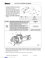
1. Disconnect the PHM Feeder Hose from
the PAT1M or PAT1.5M Tool. Remove
the tip collector from the tool.
2. Place the tool on a table top with the jaws
to the left. Using a 2.5 mm hex wrench,
remove the 4 socket head cap screws
from the left hand housing. Use a
screwdriver to remove the tool holder bolt
(3). Make note of the correct locations for
each of the screws using Figure 7.
ITEM QTY
SIZE
1
2
M3 x 25
2
2
M3 x 8
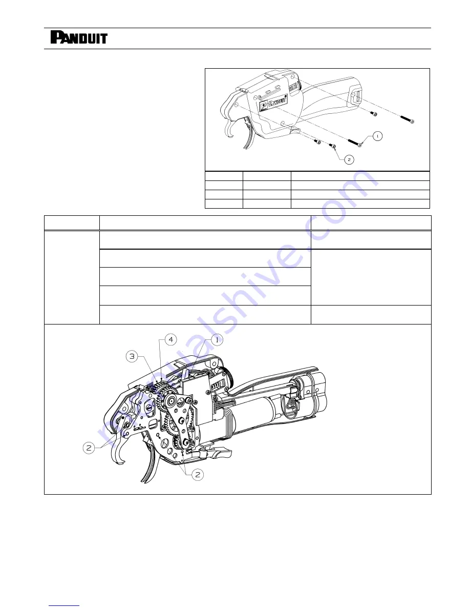
3. Perform the following maintenance
procedures shown below at the prescribed
interval:
3
1
Tool Holder Bolt
INTERVAL
MAINTENANCE PROCEDURE (See Figure 8 below)
LUBRICANT
Clean tool housings and gears of debris (not shown).
(Maintenance department must perform this procedure.)
N/A
1. Lubricate detent cam follower.
(Maintenance department must perform this procedure.)
2. Clean and lubricate all pivots and shafts.
(Maintenance department must perform this procedure.)
3. Oil shaft (1 drop) on each side of Gripper Drive Gear.
(Maintenance department must perform this procedure.)
General Purpose
Light Machine Oil
Every
100 000
cycles
4. Clean and regrease the Cam on the Front Jaw Gear.
(Maintenance department must perform this procedure.)
Schaeffer's Moly Ultra 800 EP
PANDUIT
Part # WS23132B01
4. Replace the left hand housing in position and fasten the left hand housing to the tool using the 4 socket head cap
screws and 1 tool holder bolt (removed in Step 2). See Figure 7 (above) for the appropriate screw locations.
Use a 2.5 mm hex wrench to torque the cap screws to 60 oz - in (0,42 Nm) and use a screwdriver to torque the
tool holder bolt to 80 oz - in (0,57 Nm).
5. Replace tip collector and attach PHM Feeder Hose as required to resume operation.
Fig. 7
Fig. 8
electronic components distributor

