PAT1M / PAT1.5M OPERATION MANUAL
PAT1M/PAT1.5M: PA22222A01_03
Page: 15 of 36
Dec., 2007
PAT1M/PAT1.5M TOOL
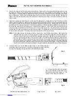
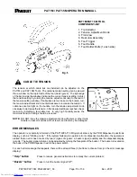
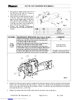
COMPONENT LIST
1. Tip Collector
2. Tension Adjustment Knob
3. Front Jaw
4. Rear Jaw Assembly
5. Tool Trigger
6. Tool Handle
7. Tool Holder Bolts (1 each side)
CABLE TIE TENSION
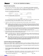
The tension at which cable ties are installed can be adjusted on the
PAT1M and PAT1.5M Tools. The cable tie tension setting can be viewed
thru a window on the top left side of the tool (See Figure 6). The right edge
of the bar (inside the window) indicates the current tension setting. Adjust
the tension setting by turning the tension adjustment knob (to the rear of
the tension setting window). If cable ties are too loose on the bundle, turn
the tension adjustment knob counterclockwise to increase the tension. If
cable ties are too tight on the bundle, turn the tension adjustment knob
clockwise to decrease the tension. After desired setting is reached, check
tension by installing a few cable ties. In very high humidity areas, the
maximum tension setting should be reduced.
NOTE:
DO NOT force the tension adjustment knob with pliers or other tools.
Greater or lesser tensions will not result, and tool may be damaged.
ERROR MESSAGES
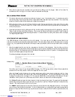
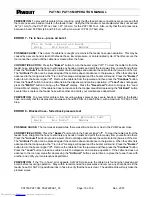
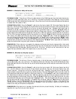
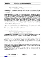
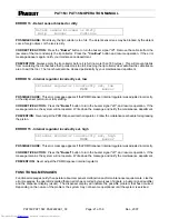
The operator is constantly informed of the PAT1M/PAT1.5M System's status by the PDM Dispenser's electronic
display, such as: "Waiting on tie". If the system fails due to operator error or dispenser malfunction, the operator is
alerted that an error has occurred by two (2) types of signals: a buzzer signal (audible) and the dispenser display
(visual). The buzzer signal volume can be adjusted by turning the faceplate of the buzzer. The buzzer is located on
the back of the PDM Dispenser next to the power switch.
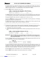
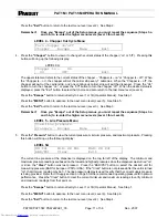
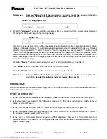
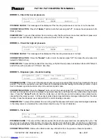
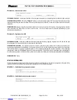
For each error message that appears, there will be at least three (3) buttons to choose from (on the error message
display):
"Help" button
Press to receive general instructions to remedy the current problem;
"Buzzer" button
Press to turn the buzzer signal "off";
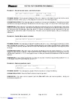
Fig. 5
electronic components distributor

