background image


PAT1M / PAT1.5M OPERATION MANUAL 


TABLE OF CONTENTS 


INTRODUCTION ..................................................................................................... 1


SYSTEM SPECIFICATIONS................................................................................... 1


PAT1M / PAT1.5M TOOLS ................................................................................ 1


PDM DISPENSER ............................................................................................. 2


PHM1 / PHM2 / PHM3 / PHM4 FEEDER HOSES ............................................. 2


ADDITIONAL COMPONENTS ........................................................................... 3


SAFETY PRACTICES............................................................................................. 3


ELECTRICAL SAFETY PRACTICES................................................................. 3


OPERATIONAL SAFETY PRACTICES ............................................................. 4


TECHNICAL SPECIFICATIONS............................................................................. 5


AIR SUPPLY ...................................................................................................... 5


ELECTRICAL SPECIFICATIONS ...................................................................... 5


OTHER SPECIFICATIONS................................................................................ 6


INSTALLATION ...................................................................................................... 6


DISPENSER MOUNTING .................................................................................. 6


SYSTEM CONNECTION ................................................................................... 6


INSTALLATION CHECKLIST............................................................................. 7


LOADING PROCEDURE ................................................................................... 7


RELOADING PROCEDURE .............................................................................. 9


SYSTEM SETUP AND MENUS ......................................................................... 9


OPERATION ......................................................................................................... 12


START UP CHECKLIST .................................................................................. 12


CABLE TIE INSTALLATION ............................................................................ 13


CABLE TIE INSTALLATION TECHNIQUES .................................................... 13


TIP COLLECTOR............................................................................................. 14


ERROR MESSAGES ....................................................................................... 15


FUNCTIONAL MESSAGES ............................................................................. 21


STATUS MESSAGES ...................................................................................... 23


MAINTENANCE .................................................................................................... 24


DAILY PREVENTIVE MAINTENANCE ............................................................ 24


EXTENDED MAINTENANCE........................................................................... 24


CLEANING THE DISPENSER EXIT SENSOR LENS...................................... 26


TOOL HOLDER BRACKET MOUNTING ......................................................... 26


MAINTENANCE LOG ...................................................................................... 27


TROUBLESHOOTING .......................................................................................... 28


ERROR MESSAGE TROUBLESHOOTING..................................................... 28


FUNCTIONAL MESSAGE TROUBLESHOOTING........................................... 30


CABLE TIE INSTALLATION TROUBLESHOOTING ....................................... 30


"QUICK REFERENCE" MENUS........................................................................... 31


SETUP MENUS ............................................................................................... 31


"ERROR MESSAGE” ADDENDUM ..................................................................... 33


"TIE IN TOOL” ADDENDUM ................................................................................ 35


Downloaded from 

Elcodis.com


electronic components distributor
 

Содержание PAT1M

Страница 1: ...ERENCE Website www panduit com Email cs panduit com EU Website www panduit com emea EU Email EMEA Toolservicecenter panduit com PANDUIT Corp USA Technical Support Tel 888 506 5400 ext 3255 Fax 630 759...

Страница 2: ...NG PROCEDURE 9 SYSTEM SETUP AND MENUS 9 OPERATION 12 START UP CHECKLIST 12 CABLE TIE INSTALLATION 13 CABLE TIE INSTALLATION TECHNIQUES 13 TIP COLLECTOR 14 ERROR MESSAGES 15 FUNCTIONAL MESSAGES 21 STAT...

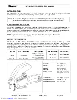
Страница 3: ...stitution may cause serious damage to the system and or injury to the operator PAT1M PAT1 5M TOOLS The PAT1M and PAT1 5M Cable Tie Installation Tools are electrically powered and controlled by the PDM...

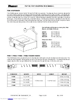
Страница 4: ...so included to collect the carrier strip remaining scrap as the cable ties are detached from the continuous strand Overall System Dispenser w scrap bin Reel Mount and Cable Tie Reel WIDTH 23 2 589 mm...

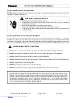
Страница 5: ...e dispenser SAFETY PRACTICES The PAT1M PAT1 5M System is pneumatically and electrically operated and electronically controlled Therefore certain safety practices must be followed ELECTRICAL SAFETY PRA...

Страница 6: ...ned Subject to the provisions of the PANDUIT service agreement OPERATIONAL SAFETY PRACTICES 1 Safety glasses must be worn at all times by all persons within ten 10 feet of any part of the system 2 DO...

Страница 7: ...ed with a male quick connect plug that will fit the listed female interchangeable couplers or their equivalents Recommended source 1 Truflate type 2 4 1 4 couplers 2 Hansen series 1000 3000 couplers 3...

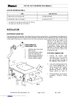
Страница 8: ...spenser and sliding the bracket down into position Refer to Page 26 for alternate mounting to walls carts or bench tops Always position the dispenser in the work area so there are no severe bends or t...

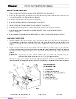
Страница 9: ...enser by positioning the larger holes in the reel mount assembly over the cap screws on the dispenser and sliding the reel mount assembly into position Tighten the cap screws to fasten the reel mount...

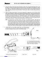
Страница 10: ...3 more cable ties are fed As each cable tie is loaded the number next to Load will decrease for each cable tie loaded The dispenser cover must be closed and latched to load or cycle the system The rot...

Страница 11: ...electric cord into the receptacle on the back of the dispenser Plug the other end into a grounded electrical outlet that matches the dispenser power requirements Refer to the Electrical Specifications...

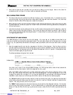
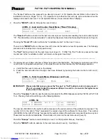
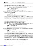
Страница 12: ...menu levels Level 3 thru Level 6 are not required except to set or to adjust the unit and are reached by the following sequence a Verify that the Level 2 menu is on the display b Press the second but...

Страница 13: ...Step 3 Remember Once you Escape out of the Setup menus you must repeat the sequence Steps 3 a and 3 b to re enter the higher menu levels Level 3 thru Level 6 LEVEL 5 Line Pressure Menu View line press...

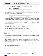
Страница 14: ...nguage Press the Escape button to return directly to Level 1 or 1B Operator Menus See Step 1 The MENU button is unavailable since Level 6 is the last Setup menu Press the Exit button to return to the...

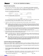
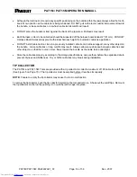
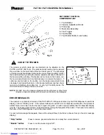
Страница 15: ...completion of the cycle release the trigger to open the rear jaw See Figure 5 on Page 15 Relocate the tool at the next desired cable tie location and repeat as required NOTE If a malfunction occurs or...

Страница 16: ...any other object on the bundle Loose cable ties or long cutoffs may result Always allow enough space between cable ties and other objects so that the tool can move freely toward the bundle as the cab...

Страница 17: ...is reached check tension by installing a few cable ties In very high humidity areas the maximum tension setting should be reduced NOTE DO NOT force the tension adjustment knob with pliers or other to...

Страница 18: ...Unload Menu display and perform the standard reloading procedure Refer to the Reloading Procedure section on Page 9 If this message appears and it is apparent that the reel is not empty then the tool...

Страница 19: ...may be caused by a jam due to bowed or misaligned cable ties feeding into the rotary receiver or a jam due to a backed up cable tie carrier strip in the carrier strip exit chute CORRECTIVE ACTION Pres...

Страница 20: ...If the cable tie does not advance to the tool jaw area after depressing the Air Burst button several times replace the feeder hose with another and notify your maintenance department PREVENTION To pre...

Страница 21: ...ct the feeder hose from the dispenser and insert the dampened end of the cotton swab into the dispenser transfer tube about 1 5 38 mm Gently move the cotton swab in and out against the top and bottom...

Страница 22: ...sensor lens may be cleaned with a cotton swab dampened with isopropyl alcohol Disconnect the feeder hose from the dispenser and insert the dampened end of the cotton swab into the end of the strap tu...

Страница 23: ...piston is not fully shifting CORRECTIVE ACTION Press the Buzzer button to turn the buzzer signal off and resume operation If the message remains the system will not operate Write down the message and...

Страница 24: ...s stuck or broken Switch X is stuck or broken POSSIBLE CAUSE This message will appear if a switch button 1 2 3 4 or the trigger is held down or stuck when the dispenser is turned on This message will...

Страница 25: ...pear System error 1 2 3 4 and 5 will appear if an internal electronic component malfunctions CORRECTIVE ACTION For System errors 1 and 2 write down the system error number and notify your maintenance...

Страница 26: ...rrier strip scrap bin Refer to the Reloading Procedure section on Page 9 EXTENDED MAINTENANCE CAUTION SAFETY GLASSES WITH SIDE SHIELDS MUST BE WORN AT ALL TIMES DURING THE MAINTENANCE OR ADJUSTMENT OF...

Страница 27: ...ollower Maintenance department must perform this procedure 2 Clean and lubricate all pivots and shafts Maintenance department must perform this procedure 3 Oil shaft 1 drop on each side of Gripper Dri...

Страница 28: ...t sensor lens Refer to Cleaning the Dispenser Exit Sensor Lens section below Every 500 000 cycles 100 cable tie reels PDM Clean and regrease piston and O rings in connection block Regrease worm gears...

Страница 29: ...T1M PAT1 5M OPERATION MANUAL PAT1M PAT1 5M PA22222A01_03 Page 27 of 36 Dec 2007 MAINTENANCE LOG DATE UNIT TOTAL COUNT MAINTENANCE PROCEDURE Downloaded from Elcodis com electronic components distributo...

Страница 30: ...Press Buzzer button to turn buzzer off 2 Set air pressure between 65 and 85 PSIG 4 5 and 5 8 bar with a maximum 10 PSI 0 7 bar drop B Connect air to dispenser Check for high air pressure Incoming air...

Страница 31: ...cable tie in tool or tool end of hose and remove cable tie if present Reconnect feeder hose and resume operation If cable tie is not found reconnect feeder hose Follow the same Corrective Action for T...

Страница 32: ...rt or other object on bundle E Tool is pulled on as the tie is being tensioned A Increase tool tension setting B Hold tool perpendicular to bundle in both directions C Dress the wires to result in a m...

Страница 33: ...BUTTON 3 Inactive BUTTON 4 Returns to LEVEL 1 SETUP MENUS LEVEL 2 SETUP MENU ACCESS Resets load and or counter 1 Press BUTTON 3 two times Reset Ld Reset Ct Exit 2 Press BUTTON 1 one time 3 Brings up...

Страница 34: ...Pressure Readings XX PSI MIN XX PSI MAX XX PSI BUTTON 1 Select unit of measure BAR PSI Clear Exit BUTTON 2 Clears present readings BUTTON 3 Inactive BUTTON 4 Returns to LEVEL 5 LEVEL 6 Language Menu...

Страница 35: ...t a Press Buzzer button then Air Burst button remove cable tie from jaws of tool Press Menu button Press Reset Load button Press Load button once and continue 4 Blocked or Dirty Tool Sensor or Tie Stu...

Страница 36: ...ic roller will cause damage 7 Jaw Sensor Error 8 Detent Sensor Blocked or Dirty 9 Blocked Hose Failed Back Pressure Test Contact Maintenance Department CABLE TIE CONDITION FACTORS INCORRECT CABLE TIE...

Страница 37: ...el 3 menu above If Tie in Tool feature is turned ON and you want to turn it OFF just repeat this process ERROR 6 Tie in Tool Tie in Tool PDM Software Revision 0 8 or higher MENU Buzzer POSSIBLE CAUSE...

Страница 38: ...ing operator corrective action same possible cause and prevention apply Tie in Tool PDM Software Revision 0 7 or lower Help Buzzer Continue CORRECTIVE ACTION Press the BUZZER button to turn the buzzer...

Отзывы: