background image

PANDUIT

®

 DPoE

™ Power Patch Panel User Manual 

Part Number: PN378E 


13


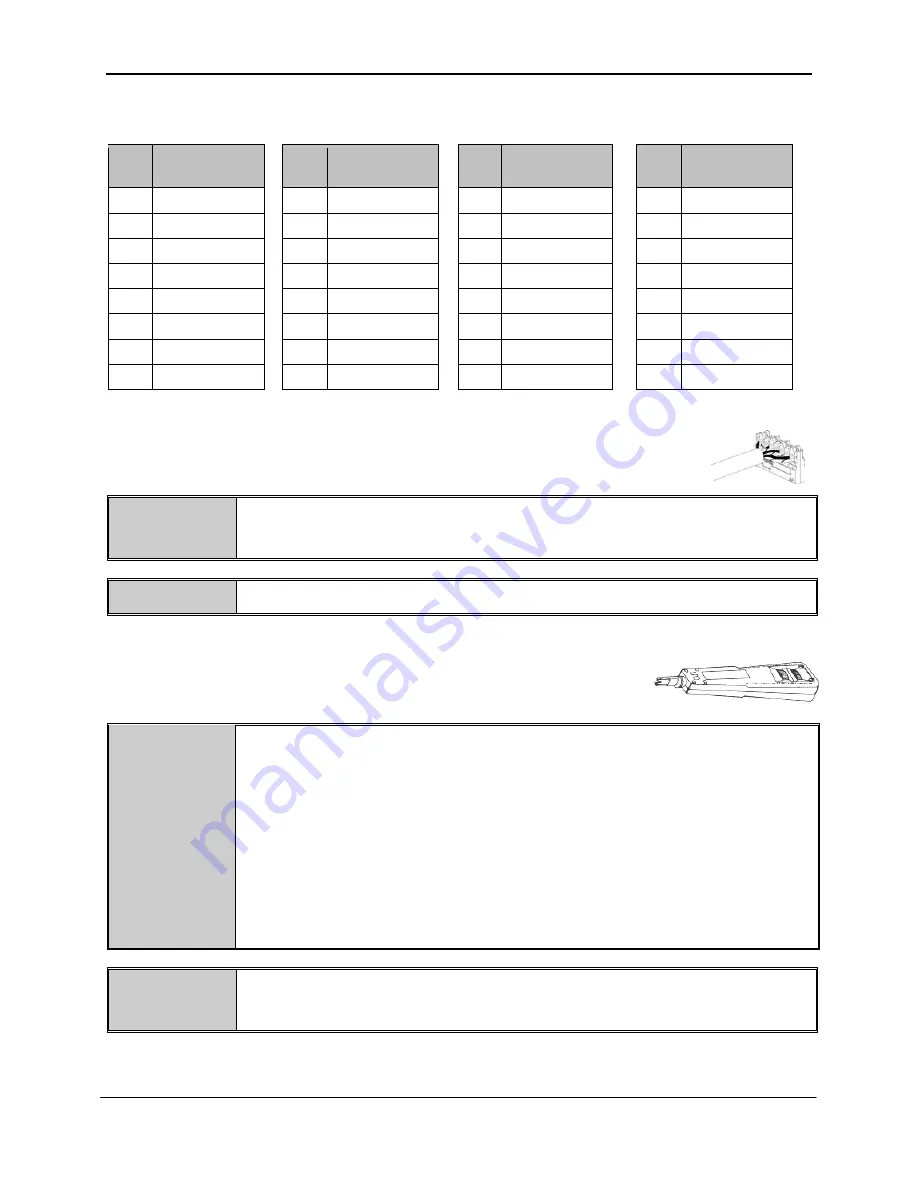
Table 4: Color-Coded Wire Position 

Table 5: Color-Coded Wire Positions  

for 802.3af-2003 Compliant Devices 


         for Alternate PoE Devices 


Pin 

Outs 

EIA/TIA 568A 


Pin 

Outs 

EIA/TIA 568B 


Pin 

Outs 

EIA/TIA 568A 


Pin 

Outs 

EIA/TIA 568B 

 5 

WHITE/BLUE 


WHITE/BLUE 

 5 

WHITE/BROWN 

WHITE/BROWN 

BLUE 


BLUE 

BROWN 

BROWN 

WHITE/GREEN 


WHITE/ORANGE 

WHITE/GREEN 

WHITE/ORANGE 

GREEN 


ORANGE 

GREEN 

ORANGE 

WHITE/ORANGE 


WHITE/GREEN 

WHITE/ORANGE 

WHITE/GREEN 

ORANGE 


GREEN 

ORANGE 

GREEN 

WHITE/BROWN 


WHITE/BROWN 

WHITE/BLUE 

WHITE/BLUE 

BROWN 


BROWN 

BLUE 

BLUE 


9.  Lay conductors into the punchdown slots for the specified port using the correct 

wiring sequence. Cable jacket removal should be minimized to the extent 
possible.  Conductor untwist should be within ½” (12.7 mm) of termination. 


WARNING: 

NEVER TOUCH UNINSULATED COMMUNICATIONS WIRING OR TERMINALS 
UNLESS THE COMMUNICATION LINE HAS BEEN DISCONNECTED AT THE 
NETWORK INTERFACE. 


NOTE: 

Never install wiring in a slot previously used for a larger gauge wire. 

 
10.  Using the recommended punchdown tool (

PANDUIT

 part number PDT110), punch down the 

connector into the punchdown slots on the back of the 

DPoE

™ Power 

Patch Panel. 


INSTALLATION 
ADVISORY: 

Ensure that cabling to powered devices is protected from inductive coupling from 
nearby power cables and other sources. 
 
Ensure that powered devices are properly installed and grounded (according to 
manufacturer’s recommendations), and all the cabling and connections are isolated 
from external surges. 
 
Observe precautions for handling electrostatic sensitive electronic devices when 
installing this product. Ensure you are properly grounded with a wrist strap or 
equivalent, while making connections to the 110 punchdown terminals on the rear of 
the product. Never make any connections to the 110 punchdown terminals when 
power is applied to the product.


NOTE: 

When installing cabling and making connections to the DPoE panel, follow all local 
standards, as well as the applicable TIA-942 standards and IEEE 802.3 (Ethernet) 
standards. 


Содержание DPOE12U1XY

Страница 1: ...nical photocopying recording or otherwise without written permission from PANDUIT No patent liability is assumed with respect to the use of the information contained herein Although every precaution has been taken in the preparation of this book PANDUIT assumes no responsibility for errors or omissions Neither is any liability assumed for damages resulting from the use of the information contained...

Страница 2: ...from another country The products presented in this user s guide are not designed intended authorized or warranted to be suitable for use as components in systems used in any life support or critical applications including but not limited to any applications intended to support or sustain life any medical applications any systems used for commercial transportation or nuclear facilities or any othe...

Страница 3: ...e Requirements 19 Installing the DPoE Element Manager Software 20 Connecting the DPoE Element Manager Host Computer to the DPoE Power Patch Panel 21 DPoE Element Manager Operation 21 Graphical User Interface 22 Additions or Changes to UserName Password 23 Panel Discovery 24 Subnet Search 25 IP Range Search 25 Provisioning the Panel 27 Administering Port and Panel level Information 31 Edit Panel In...

Страница 4: ...igures Figure 1 DPoE Power Patch Panel Front View 6 Figure 2 DPoE Power Patch Panel Rear View 7 Figure 3 System Level Opening Screen 22 Figure 4 View Panel Screen 31 Figure 5 View Device Screen SNMP Settings 32 Figure 6 Edit Panel Screen 32 Figure 7 Active Port Indicator Screen 33 Figure 8 View All Ports Screen 40 Figure 9 View Individual Port Screen 41 Figure 10 View Message Log Screen 43 Figure ...

Страница 5: ...2 DPoE Element Manager Log Messages 49 Table 13 DPoE Power Patch Panel Firmware Update LED Status 52 Table 14 Power Supplies Available from PANDUIT 53 Table 15 Package Contents 53 Table 16 PANDUIT Corp Contact Information 54 Table 17 Color Coded Wire Positions for 802 3af 2003 Compliant Devices 56 Table 18 Color Coded Wire Positions for Alternate PoE Devices 57 Table 19 DPoE Power Patch Panel Powe...

Страница 6: ...hout the need for separate passive patch panels NOTE DPoE Power Patch Panels cannot be used for analog or non Ethernet devices While the DPoE Power Patch Panel may be used as a standalone device it can be configured and monitored from a centralized software application the DPoE Element Manager This management software application allows network operators to remotely perform routine maintenance and...

Страница 7: ...l devices and allows centralized power management by the network operator Combining PoE Power with patch panel functionality for Ethernet Connections Other vendors use a separate Power Hub architecture which doesn t replace the need for additional non powered patch panels The DPoE Power Patch Panel combines these two functions into a 1 RU high package This reduces needed rack space by at least 50 ...

Страница 8: ...he event of low power conditions a NMS working in conjunction with the DPoE Power Patch Panels can use the pre established port priorities to ensure mission critical ports on the network of panels continue to receive PoE power as long as possible Easier Local Management Multi colored LEDs on the DPoE Power Patch Panel allow technicians to instantly know the status of each port Additional LEDs refl...

Страница 9: ...50 watt rectifier for use in the DPOEPWRCU chassis CORD A Power cord for Australia CORD E Power cord for Europe CORD S15 Power cord for North America CORD J15 Power cord for Japan CORD U Power cord for the U K Power Requirements 1 Isolated SELV output with 1500 volt isolation to ground 2 Minimum 49 volts available at panel to meet IEEE 802 3af specifications 3 10 amp 4 Proper fusing to protect int...

Страница 10: ... Do not exceed a total length of 35 feet Verify the above contents arrived in good condition If not contact PANDUIT Technical Support Table 3 PANDUIT Corporation Contact Information PANDUIT Technical Support Fax 1 708 444 6993 E mail cs PANDUIT com For Installation Instructions in Local Languages and Technical Support http www panduit com Support Software index htm Worldwide Subsidiaries and Sales...

Страница 11: ... green and yellow striped grounding strap to the panel via the unthreaded hole nearest the power connector Next install the panel into a grounded rack using the appropriate screw set provided to ensure proper grounding between the panel and the rack Finally attach the loose end of the grounding strap to the rack within the same position as the panel PANDUIT Structured Ground Kits for Data Center R...

Страница 12: ...y chain fashion as shown Once all of the connections are made the DPoE Element Manager or another Network Manager will be able to communicate with all the panels over this daisy chain of connections See Provisioning the Panel for more information Connecting the Powered Devices 7 Remove 1 inch 25 4 mm of cable jacket being careful not to damage the conductors 8 Fan out all four twisted pairs in the...

Страница 13: ...UNICATION LINE HAS BEEN DISCONNECTED AT THE NETWORK INTERFACE NOTE Never install wiring in a slot previously used for a larger gauge wire 10 Using the recommended punchdown tool PANDUIT part number PDT110 punch down the connector into the punchdown slots on the back of the DPoE Power Patch Panel INSTALLATION ADVISORY Ensure that cabling to powered devices is protected from inductive coupling from ...

Страница 14: ...he power harness wires to the supply wires A crimping tool such as the PANDUIT part number CT 100 may be used The provided butt splices PANDUIT part number BSV14X support 14 16 AWG solid or stranded wire WARNING The power supply connections are polarized The DPoE Power Panel will not function if power is wired improperly For Maximum power the overall length of the wire between the power supply and...

Страница 15: ...status LED above the IN management port will stay amber and the network status LED above the OUT management port will turn off This indicates that the panel is actively requesting address information from the network Once this information is received this could take up to a minute the network status LED above the IN management port will turn on or start flashing green as data is transmitted and re...

Страница 16: ...tandards Also try to connect the device to another port to see if it powers on 4 The port Administration Control setting is set to OFF in the DPoE Element Manager The DPoE Element Manager must be used to set the port Administration Control to ON See Edit Port Information for more information The panel status LED stays solid red after power is connected and over 20 seconds has elapsed 1 The power s...

Страница 17: ...iption Status of Power Ports Off Off No Power is being supplied to the panel Power is NOT being delivered to the ports on the panel Green Flashing System operating normally Power may be delivered down the ports on the panel as configured Amber Solid Out of voltage range condition Less than 46VDC or more than 57VDC is being supplied to the panel Power is NOT being delivered to any ports on the pane...

Страница 18: ...should be checked to ensure proper wiring has been followed Power is NOT being delivered down this port on the panel Table 9 Network Status LED Indications LED Color Network LED Status Description Notes Off Off No connection to the management system If the system is otherwise operating normally and an Ethernet 10 100 cable is connected this could be an issue with the panel s management interface G...

Страница 19: ...essor or equivalent RAM 128 MB of RAM 256 MB recommended Hard Disk Space 45 MB of available hard disk space Network Access 10 100 Ethernet card CD ROM Drive Software Operating System Any Windows Vista of the following Windows XP Professional Service Pack 1 or later Windows XP Home Edition Service Pack 1 or later Windows 2000 Service Pack 4 for Windows 2000 Support Applications 1 Microsoft NET Fram...

Страница 20: ...ile Launch exe Once all required support software is installed the installation screen will be displayed For security purposes the network operator will then be given the opportunity to restrict the DPoE Element Manager to the administrator UserName only default or whether other users of this PC can access it Once this selection is made the installation process completes in only a few minutes Afte...

Страница 21: ...n to anything IMPORTANT Directly connecting a PC to the panel will either require the PC to be setup as a DHCP Server or require the DPoE Power Patch Panel to be setup for static IP addressing The panel factory default setting is DHCP addressing If a panel is changed to static IP addressing make sure the static IP address is recorded no communication to the DPoE Power Patch Panel can be done witho...

Страница 22: ...nels Likewise configuration changes can be made at the network panel or port level The Tree View of the Network area provides a hierarchical display of each patch panel within the network using the configurable names assigned by the network operator Multiple patch panels physically wired into a single rack are grouped on the screen under the configurable name of that rack Using the computer mouse ...

Страница 23: ...al time display indicates the communication status between the DPoE Element Manager and the DPoE Power Patch Panels By adding additional UserNames to the DPoE Element Manager the network operator can allow access to the system via the DPoE Element Manager by other users without the need for sharing a single UserName Password among multiple users Additions or Changes to UserName Password The Users ...

Страница 24: ...can be used to collect this information during installation When installing multiple DPoE devices simultaneously it is very important to record the MAC address for each panel Since multiple panels will return the same factory default settings to the Discover capability the MAC address which is written on a sticker on the back of each DPoE Power Patch Panel is unique and will allow the network oper...

Страница 25: ...ger and the DPoE Power Patch Panels For security reasons these fields should be changed from their defaults Care should be taken however as the SNMP Community fields are case sensitive and will read inadvertently mistyped spaces or characters Once any subnetwork changes are entered if necessary check those subnets to be searched and click the Start button When Start is selected the Scanning in pro...

Страница 26: ...E Power Patch Panel information will be populated in the DPoE Element Manager the Start button will initiate the Discover capability TIP In addition to the Discover capability the DPoE Element Manager also supports a Refresh capability which collects the information stored in each Patch Panel and verifies that it is consistent with the information in the DPoE Element Manager refer to Refresh the N...

Страница 27: ...ering its specific attributes into the DPoE Element Manager is an integral part of the provisioning activity Loading this information into the DPoE Element Manager enables it as well as Network Management Software to be used in an effective working manner It is highly recommended that the Network Administrator invest the effort to provision the DPoE device in the following manner 2 Once the DPoE P...

Страница 28: ...may be a problem with the network connection itself The DPoE Element Manager reflects physical location information and power status based on the last time this information was refreshed In order to work with the latest physical location information and power status you should refresh the panel power midspan information using the Refresh icon on the Element Manager before making any modifications ...

Страница 29: ...e used to associate the discovered device with the information contained on the installation worksheet and the Panel Attributes can now be entered 6 Double click on the row in the table containing the first newly discovered panel After the panel information is gathered from the panel the View Panel Screen will open and will look like this 7 Select the Edit DPoE device Info and the following form w...

Страница 30: ...PoE Power Patch Panel Fill out per the example shown on right Click the OK button and the Device Physical Location information will be added to the device attributes field 8 Once all of the desired information is entered into the Panel Attributes field click the Save button and this information will be saved The panel and the rack images will be shown in the DPoE Element Manager Tree View of the N...

Страница 31: ...e intuitive physical location information that is stored in each panel The DPoE Element Manager makes it easy to administer the deployed network of DPoE Power Patch Panels When a specific panel is selected in the Tree Level View of the Network on the system level opening screen the DPoE Element Manager automatically retrieves the latest power and LED information from the selected panel and display...

Страница 32: ... set for this device This screen cannot be used to modify the configuration SNMP information The SNMP configuration can be edited selecting the Edit Panel Info button on the right side tool bar Edit Panel Information In addition to the Edit Panel Info button on the tool bar the Edit Panel option under the Devices pull down menu provides an easy mechanism to perform this task Figure 6 Edit Panel Sc...

Страница 33: ...mple port 5 and the selected port will highlight with a flashing yellow indicator You will receive a dialog box on screen stating that the EMS is obtaining the latest information for the selected port The port information will be displayed for this example port 5 and the selected port will continue to be highlighted with the flashing yellow indication Figure 7 Active Port Indicator Screen The Port...

Страница 34: ...he Rack Space Position field refer to Provisioning the Panel for more information Once these values are set in the DPoE Element Manager this information will be transmitted and stored in the DPoE Power Patch Panels Two additional fields are available on this screen and affect the operation of the panel The first field the Power Threshold allows the network operator to configure the available power...

Страница 35: ...ect the number of times a SNMP message retry occurs prior to receiving this Timeout error message The SNMP Retry function enables a choice of the amount of times the SNMP message is retried Once a device has been discovered the settings selections can be made from the pull down menu by choosing Tools and then Settings The Settings pop up screen will appear allowing you to set SNMP retries from 0 t...

Страница 36: ...m one panel to another The Copy Panel and Paste Panel options under the Tools pull down menu provide an easy mechanism to perform this task Once a panel is highlighted in the Tree View of the Network area on the system level opening screen the View Panel Screen for that panel will appear Using the Copy Panel capability will copy all panel level information into a buffer By then selecting another p...

Страница 37: ...into new units prior to configuration A dialog box will appear allowing device information to be exported for All Devices Devices that are in the Selected Rack Room or for the Selected Device The Refresh Data box prompts the system to obtain the most recent information from the device After hitting OK a dialog box will appear requiring a file name and desired location to save the file The first da...

Страница 38: ...database in memory is erased Restoring Device and Port Information The Import function allows retrieval of saved device and port data that has been previously extracted and saved to a file using the Export function Once a device has been discovered and identified in the DPoE Element Manager retrieved device information may be imported into a discovered device using the Import Device Information fu...

Страница 39: ...E device If a device is selected incorrectly it is possible to overwrite a 24 port configuration information into an 8 port device only the data representing the first 8 ports will be used Conversely and 8 port device can overwrite information into a 24 port unit This may be desirable for device level configuration information e g owner location etc but may be undesirable for port information View...

Страница 40: ...n will bring up the configuration information for that individual port This is the same screen that will appear by double clicking an individual port on the Visual Display of the Front Panel portion on the View Panel Screen TIP By holding down the ctrl key the network operator can select multiple ports on the same Power Patch Panel Then by selecting the Edit Port Properties button on the Tool Bar ...

Страница 41: ...Port Screen Clicking on the Edit button will bring up a screen to edit individual ports on a DPoE Power Patch Panel If the network operator were simultaneously configuring multiple ports the Multiple Port Edit screen would instead appear and any values not overwritten would be left unchanged ...

Страница 42: ...or a closed circuit condition and will not apply power until a load is detected across the circuit In Forced mode the device port will deliver power without performing a detection classification If nothing is detected within the circuit then no device connected traps will continuously be generated until a load is connected WARNING Forced power mode is not a normal operating condition Although Forc...

Страница 43: ...ntial listing of all messages received by the DPoE Element Manager displaying them in a first in first out manner That is the most recently received messages are listed at the top of the window and the older messages are pushed down toward the bottom of the window The rewind and fast forward buttons in the right half of the tool bar for the Message Log area are used to navigate through the message...

Страница 44: ...AC addresses Panel name or range of panel names Port number or range of port numbers Specific message types Export Log By clicking on the Export Log button the operator is given the option of exporting the log file related to particular panel rack or the entire log to a file Clear Log By clicking on the Clear Log button the operator will be given the opportunity to export the log before erasing th...

Страница 45: ...l the racks in a panel or a single panel within a rack By using the E mail mechanism the network operator can assign specific e mail addresses to be notified of network events For example the DPoE Element Manager can be configured to send e mail messages to one or more e mail addresses in the event of configuration changes incoming alarms or other events within the network of DPoE Power Patch Pane...

Страница 46: ...panel of the E mail Settings the right panel is used to select which message categories will be sent to that e mail address refer to DPoE Element Manager Log Messages for more information on each of these message types NOTE The same category of events may be selected for multiple destination e mail addresses The Edit button is used to change the e mail address of an already assigned e mail address...

Страница 47: ... User Manual Part Number PN378E 47 Panel level searches can be conducted by any combination of MAC address Panel Name Rack Name Rack Space Location Hardware Version IP Address Physical Location Power Supply Location Firmware Version ...

Страница 48: ...N378E 48 Port level searches can be conducted by any combination of Port Number PD Type Work Area Location Administration Control Detection Status Power Priority Power Classification Legacy Control NOTE The Link Information tab is not supported at this time ...

Страница 49: ...t Device Power Above Threshold Major The power consumption at the device has risen above the Power Warning Threshold Device Power Below Threshold Major The power consumption at the device has fallen below the Power Warning Threshold Fuse Blown Critical The internal safety fuse has opened due to a catastrophic failure of the unit Port Physical Location Changed Advisory Location information of one o...

Страница 50: ... panels in the racks in the same fashion as they are wired in the network racks Either the rack slots are numbered from with the highest rack positions at the top Descending or the highest rack positions at the bottom Ascending By setting this parameter appropriately the rack level displays presented by the DPoE Element Manager will show the DPoE Power Patch Panels in their installed top to bottom...

Страница 51: ...ust point to the directory where the new DPoE product file is stored 3 The Update Firmware under the option Tools pull down menu opens a window that identifies the IP address device type and device name The window as shown in the DPoE Element Manager Firmware Update Screen can then be used to initiate the TFTP firmware update by the network operator entering the firmware filename and IP address of...

Страница 52: ... Ethernet Switch Initialization 00 01 seconds Amber Solid DHCP Initialization 01 100 seconds Green Blink DHCP complete Red rapid Blink Green Blink Image transfer and update in progress 5 7 minutes Red slow Blink CRC code 4 seconds Red Solid Image update complete END Green Slow Blink Application Running The Exiting the DPoE Element Manager Exit option under the File pull down menu or the button wil...

Страница 53: ...EPWRR1250 1250 watt rectifier for use in the DPOEPWRCU chassis CORD A Power cord for Australia CORD E Power cord for Europe CORD S15 Power cord for North America CORD J15 Power cord for Japan CORD UPWR Power cord for the U K Package Contents Each DPoE Shielded Power Patch Panel is shipped in a box that includes the following Table 14 Package Contents Item Quantity Notes DPOE24S1XY Power Patch Pane...

Страница 54: ... S 30 The PAN TY S are used to secure the shielded cable to the rear shield and secure the shield Verify the above contents arrived in good condition If not contact PANDUIT Technical Support Table 15 PANDUIT Corp Contact Information PANDUIT Technical Support Fax 1 708 444 6993 E mail cs PANDUIT com For PANDUIT Product Installation Instructions http www panduit com Support Software index htm Worldw...

Страница 55: ... at the planned rack position 4 Record the rack space position on the Installation Worksheet 5 Prepare the shielded cables for termination using the figures appropriate for the type of cable used Caution Do not damage conductors To ensure the highest shielding effectiveness cut 1 5 38 1 mm of copper tape included in 4 strips inside the Power Patch Panel Installation Kit and wrap it around the cabl...

Страница 56: ...esponding to a EIA TIA 568A or EIA TIA 568B configured data pairs wiring sequence must be used Table 16 Color Coded Wire Positions for 802 3af 2003 Compliant Devices Pin Outs EIA TIA 568A Pin Outs EIA TIA 568B 5 WHITE BLUE 5 WHITE BLUE 4 BLUE 4 BLUE 1 WHITE GREEN 1 WHITE ORANGE 2 GREEN 2 ORANGE 3 WHITE ORANGE 3 WHITE GREEN 6 ORANGE 6 GREEN 7 WHITE BROWN 7 WHITE BROWN 8 BROWN 8 BROWN NOTE The DPoE ...

Страница 57: ...ITE GREEN 1 WHITE ORANGE 2 GREEN 2 ORANGE 3 WHITE ORANGE 3 WHITE GREEN 6 ORANGE 6 GREEN 7 WHITE BLUE 7 WHITE BLUE 8 BLUE 8 BLUE 7 For best performance the cable pair twists should be maintained as close as possible to the point of termination Punchdown the conductors with a 110 Punchdown tool PANDUIT part no PDT110 Record port information on the DPoE Power Patch Panel Installation Worksheet PANDUI...

Страница 58: ... be able to communicate with all the panels over this daisy chain of connections See Panel Provisioning the for more information Power Requirements 10 If the panel is being powered by an individual power supply such as a DPoE Power Patch Panel Power Supply See page 9 Table 1 Power Supplies Available from PANDUITfor a list of available powering options skip to Powering Up The DPoE Power Patch Panel...

Страница 59: ...ical Support for more information about connecting the redundant B Feed Power 13 Lightly tug on the butt spliced connections to verify that the butt splices are secure 14 Plug the connector into the back of the DPoE Patch Panel 15 Attach the top and bottom rear shields to the panel using the tabs on the shields Be sure that the compliant conductive foam on the shields is in contact with the copper...

Страница 60: ...is configured for Dynamic Host Control Protocol DHCP address assignment and a cable is NOT connected to the IN management port on the rear of the panel the panel status LED will blink green If the DPoE Power Patch Panel is configured for DHCP address assignment default factory setting the network status LED above the IN management port will stay amber and the network status LED above the OUT manag...

Страница 61: ...rom the front of the unit If the panel were set to static IP addressing rather than DHCP the network status LED above the IN management port will immediately turn green If the panel were set to static IP addressing rather than DHCP the panel status LED will flash green and continue flashing as long as power is applied to the unit ...

Страница 62: ...eet IEEE 802af specifications Typical per port power output IEEE 802 3af 2003 compliant power 15 4 watts port 46VOUTDC 350mA Maximum overall power consumption 490 Watts 57VINDC 8 6 A Mounting Option Mounts to standard EIA 19 rack or 23 rack when used with panel extender brackets PANDUIT part number PEB1 Extender brackets are not included with the DPoE Power Patch Panel Packaging See page 9 Table 2...

Страница 63: ...ical and Electronic Engineers IP Internet Protocol LED Light Emitting Diode MAC Media Access Control MHz Megahertz NMS Network Management System o d Outside Diameter PC Personal Computer PD Powered Device PoE Power Over Ethernet SNMP Simplified Network Management Protocol UPS Uninterruptible Power Supply V2C SNMP Version 2 Communications VDC Volts Direct Current ...

Страница 64: ...products freetools index aspx TFTPServer 3Com Freeware ftp ftp 3com com pub utilbin win32 3cs117 zip Weird Solutions Shareware http www weirdsolutions com weirdSolutions files products desktopSoftware desktopTftp tftp_desktop_free exe WinAgents 30 day Trial http www winagents com en products tftp server index php For this application note we will use the free Solar Winds TFTP server Go to the Sola...

Страница 65: ...PANDUIT DPoE Power Patch Panel User Manual Part Number PN378E 65 Click Yes Click Next ...

Страница 66: ... Patch Panel User Manual Part Number PN378E 66 Click Finish Now run the program Move your mouse to the Start Menu lower left corner Start Menu All Programs Solar Winds Free Tools TFTP Server Go to the File Configure menu ...

Страница 67: ...n configured correctly After the download works you will see something like this on the screen that shows the file transfer Note If you are using a TFTP server from another vendor they may have some user settable options If available please set the timeout to 2 seconds and the maximum retransmits to 20 The Solar Winds TFTP server does not make these settings available to the user ...

Отзывы: