


AT-OME-ST31A
16
OUTPUT
DC 24V
INPUT
2
3
RS-232
AT-OME-ST31A
1
L
R
AUDIO OUT
LAN
IP MODE
RESET
INPUT
FW
3
2
1
PWR
LINK
OMEGA
TM
AT-OME-ST31A
DISPLAY
OUTPUT
DC 24V
INPUT
2
3
RS-232
AT-OME-ST31A
1
L
R
AUDIO OUT
LAN
IP MODE
RESET
INPUT
FW
3
2
1
PWR
LINK
OMEGA
TM
AT-OME-ST31A
DISPLAY
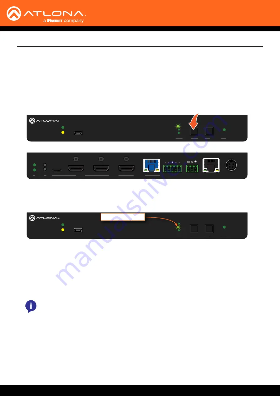
1.
Press and release the
INPUT
button on the front panel to cycle between
INPUT 1
(USB-C),
INPUT 2
(HDMI), and
INPUT 3
(HDMI)
i
nputs. The
USB-C
input (INPUT 1) is the factory-default setting.
After the
INPUT
button is pressed, the INPUT LED indicator will display the currently active input. In this
example,
INPUT 2
(HDMI) is the active input and is indicated by LED indicator
2
, on the front panel.
2.
Press the
INPUT
button again to switch to
INPUT 3
.
3.
Press the
INPUT
button once more to return to
INPUT 1
.
Manual input switching can also be performed under the
of the web server, by
clicking the
Input Selection
drop-down list and selecting the desired input. In addition, the
x1AVx1
command
can also be used. Refer to the
Application Programmer’s Interface
for more information.
Device Operation
Switching between any of the three input ports can be performed either manually or automatically. The following
section covers both methods.
Input Switching
Manual Switching
NOTE:
The AT-OME-ST31A retains the currently selected input, even after the unit is powered-off
then powered-on.
INPUT 2 LED indicator


