27
PERIODIC INSPECTION
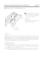
Removal of the Top Plate and Side Plate.
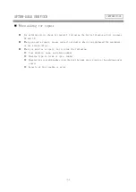
Cautions for Dielectric Strength Test and Insulation Resistance Test Since this machine uses
many semiconductors, including thyristors, an imprudent dielectric strength test or insulation
resistance measurement could lead to a trouble of the equipment.
When you conduct these tests in compliance with your company regulations, he sure to observe
the following points.
1
Remove three cables coming from the switch box and connected to three input terminals. Tie
the three input terminals altogether with a conductor to Short-circuit them.
2
Tie three input terminals of the magnet switch altogether with a conductor to short-circuit
them. Also, tie three input terminals of the magnet switch altogether with a conductor to
short-circuit them.
3
Remove two output cables connected to two output terminals. Tie the two output terminals
with a conductor to short-circuit them.
4
Using conductors, tie between the anode and cathode of the thyristors (SCR1-SCR6) to
short-circuit them. The conductors used in ①,② and ③ should have a sectional area of
about 1.25 mm
2
.
5
Remove the case grounding terminal (wire number 9). (The 200KR2/350KR2 has the case grounded,
using fasten terminals in two places of the rack frame.
The 500KR2 has the case grounded, using a fasten terminal on the magnet mounting plate for
the primary side, and another fasten terminal on the rack frame(bottom plate) for the
secondary side.)
6
Remove everything such as wire feeder, etc. and leave the welding power unit as a single
unit.
7
Remove all connectors from the printed circuit board.
Now that you have completed those preparations, you can proceed with the above-mentioned tests
without worrying about troubles or damages on the equipment.
①Remove of the top plate. (4 bolts)
②Remove the side plates.
(9 bolts each on the left and right)
Tips
FOR YOUR INFORMATION


