Part Description
© Panasonic Industrial Devices SUNX Co., Ltd. 2017
16
●
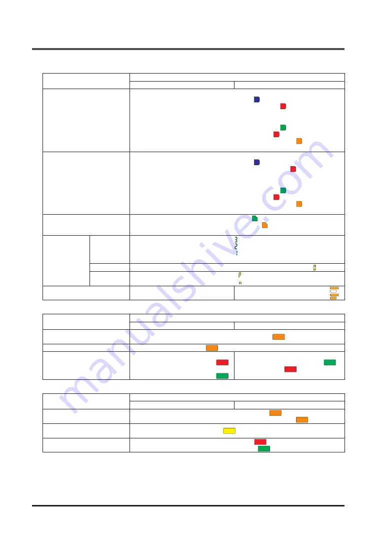
Emitter/receiver common
Name
Function
Line synchronization
Optical synchronization
Upper application indicator
(Blue / Red / Green / Orange)
(Note 1)
<When beam axis alignment mode is set>
Control output (OSSD 1 / 2) ON: Lights blue “
”
When top end beam channel receives light: Lights red “
”
When top end beam channel is blocked: Turns OFF
<When application mode is set>
When application indicator input 1 is ON: Lights green “
”
When application indicator input 2 is ON: Lights red “
”
When application indicator input 1 / 2 are ON: Lights orange “
”
When application indicator input 1 / 2 are OFF: Turns OFF
Lower application indicator
(Blue / Red / Green / Orange)
(Note 1)
<When beam axis alignment mode is set>
Control output (OSSD 1 / 2) ON: Lights blue “
”
When bottom end beam channel receives light: Lights red “
”
When bottom end beam channel is blocked: Turns OFF
<When application mode is set>
When application indicator input 1 is ON: Lights green “
”
When application indicator input 2 is ON: Lights red “
”
When application indicator input 1 / 2 are ON: Lights orange “
”
When application indicator input 1 / 2 are OFF: Turns OFF
Stable light reception indicator
(Green / Orange)
When light reception is stable: Lights green “
”
When light reception is unstable: Lights orange “
”
When light is blocked: Turns OFF
Digital indicator
(Green / Yellow)
Received
light intensity
(Green)
Light intensity / Level 3: Lights green “
”
Light intensity / Level 2: Lights green “
”
Light intensity / Level 1: Lights green “
”
When light is blocked: Turns OFF
Error (Yellow)
Normal operation: Turns OFF, Error: Yellow number blinks or lights “
”
Polarity
(Yellow)
When PNP output is set: Lights yellow “
” (only during startup)
When NPN output is set: Lights yellow “
” (only during startup)
Frequency indicator (Orange)
-
When frequency 1 is set: Lights orange “
”
When frequency 2 is set: Lights orange “
”
●
Emitter
Name
Function
Line synchronization
Optical synchronization
Light emission intensity control
indicator (Orange) [CTRL]
Short mode: Turns OFF, Long mode: Lights orange “
”
Test indicator (Orange) [TEST] During test: Lights orange “
”, Normal operation: Turns OFF
Operation indicator
(Red / Green) [OP]
Control output (OSSD 1 / 2) OFF:
Lights red “
”
Control output (OSSD 1 / 2) ON:
Lights green “
”
Normal operation: Lights green “
”
Error: Lights red “
”
●
Receiver
Name
Function
Line synchronization
Optical synchronization
Function setting indicator
(Orange) [FUNC]
Communication module connected: Blinks orange “
”
Blanking function or parallel connection used: Lights orange “
” (Note 2)
Interlock indicator (Yellow)
[LOCK]
Interlock activated: Lights yellow “
”, All other times: Turns OFF
OSSD indicator (Red / Green)
[OSSD]
Control output (OSSD 1 / 2) OFF: Lights red “
”
Control output (OSSD 1 / 2) ON: Lights green “
”
Notes: 1) In the case of optical synchronization, the upper application indicator and lower application indicator on
the emitter remain OFF.
2) For details on the blanking function and parallel connection, refer to
“3-11 Functions That Can be Set
Using the Optional Communication Module SF4D-TM1”
.
3) Names in brackets [ ] are names that are indicated on the device.
Содержание WUME-SF4D-4
Страница 2: ... Panasonic Industrial Devices SUNX Co Ltd 2017 2 MEMO ...
Страница 126: ...Functions Panasonic Industrial Devices SUNX Co Ltd 2017 126 MEMO ...
Страница 130: ...Maintenance Panasonic Industrial Devices SUNX Co Ltd 2017 130 MEMO ...
Страница 140: ...Troubleshooting Panasonic Industrial Devices SUNX Co Ltd 2017 140 MEMO ...
Страница 174: ... Panasonic Industrial Devices SUNX Co Ltd 2017 174 MEMO ...


