PA Board SOS Detection Circuits
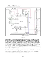
Over-Voltage Detection of Main Voltage (10 Blinks)
Figure 39
The transistor Q5644 monitors the MAIN_3.3V, MAIN_5V, MAIN_9V, and MAIN_2.5V
lines. If any of these supply voltages becomes excessive, the inline zener diode goes
into conduction and turn on transistor Q5644. As a result, a voltage drop appears at the
base of Q5641, causing it to turn on and
output a high to pin 111 of the MPU, IC4005, to
trigger the SOS condition.
43
Содержание TH37PX50U - 37" HD PLASMA TV
Страница 40: ...SC board Waveform Figure 30 SU And SD Board Shift Registers Figure 31 35 ...
Страница 43: ...SS Board Schematic Figure 33 SS Board Waveform Figure 34 38 ...
Страница 66: ...Adjustment Volume Locations Figure 53 61 ...
Страница 67: ...Test Point Locations Figure 54 62 ...
Страница 71: ...Scan and Sustain Drive Waveform Figure 55 Scan and Sustain Drive Check points Figure 56 66 ...


