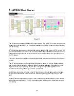
Audio Input Selection Block Diagram
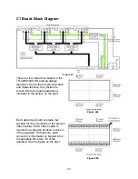
Figure 21
IC2605 of the H board handles the audio selection of all inputs. Audio signals from the
digital tuner and the HDMI receiver board (DV board) pass through the DG board and
enter IC2605 of the H board via the connector H2/DG2. The selected audio signals are
output to the DG Board without alteration. The audio output at pin 38 and 40 of the
connector H2/DG2 passes through the DG board and enters the DT Board for
conversion into PCM (Pulse Code Modulation) audio. Pins 29 and 30 of IC2605 provide
the audio for the program out jack. IC2608 contains the BBE VIVA technology circuit
used for sound processing.
26
Содержание TH37PX50U - 37" HD PLASMA TV
Страница 40: ...SC board Waveform Figure 30 SU And SD Board Shift Registers Figure 31 35 ...
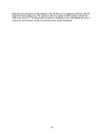
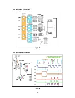
Страница 43: ...SS Board Schematic Figure 33 SS Board Waveform Figure 34 38 ...
Страница 66: ...Adjustment Volume Locations Figure 53 61 ...
Страница 67: ...Test Point Locations Figure 54 62 ...
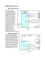
Страница 71: ...Scan and Sustain Drive Waveform Figure 55 Scan and Sustain Drive Check points Figure 56 66 ...


