background image

55

English

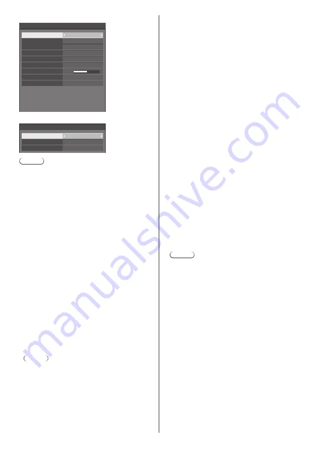
When PC is selected

59.95    Hz
154.00    MHz
1920x1200/60

74.04    kHz

0

Signal

Input resolution

V-freq.

H-freq.

Dot clock freq.

Input level

Signal format

Auto

MPEG noise reduction

Noise reduction

Off

Auto

Dynamic backlight control

Off

Frame creation

Off

Sync

Auto

Cinema reality

Off

Component/RGB-in select

RGB

When USB / MEMORY VIEWER is selected

Signal

Noise reduction

MPEG noise reduction

Auto

Off

Frame creation

Off

Note

● 

[Signal] setup menu displays a different setting 

condition for each input signal.

● 

Menu that cannot be adjusted is greyed out.


[Component/RGB-in select]

This menu is displayed at PC signal input.
Select to match the signals from the source 

connected to PC IN terminal.

[Component]:

YP

B

P

R

/YC

B

C

R

 signals

[RGB]:

RGB signals


[

YUV/RGB-in select

]

This menu is displayed at HDMI 1, HDMI 2, 

DisplayPort, DIGITAL LINK, DVI-D IN and SLOT 

inputs.
Select to match the signals from the source 

connected to each terminal.

[Auto]:

YUV/RGB setting is automatically switched.

[

YUV

]:

YUV signals

[RGB]:

RGB signals

Note

● 

Set for each input terminal (HDMI 1, HDMI 2, 

DisplayPort, DIGITAL LINK, DVI-D IN, SLOT).


[Sync]

This menu is displayed at PC IN input.

Setting RGB/PC sync signal

[Auto]:

The H and V sync or synchronized signal is 

automatically selected. When both of them have 

sync signal, H and V sync will be selected.
When displaying CS signal, connect to HD input 

terminal.

[on G]:

Uses a synchronized signal on the Video G 

signal, which is input from the G connector.

[

HV sync

]:

Uses a synchronized signal on the Video HD/VD 

signal, which is input from the HD/VD connector.

Setting Component sync signal

[Auto]:

The H and V sync or synchronized signal is 

automatically selected. When both of them have 

sync signal, H and V sync will be selected.
When displaying CS signal, connect to HD input 

terminal.

[on Y]:

Uses a synchronized signal on the Video Y 

signal, which is input from the Y connector.

[

HV sync

]:

Uses a synchronized signal on the Video HD/VD 

signal, which is input from the HD/VD connector.


[Cinema reality]

Faithfully reproduces videos shot with cinema films. 

Set this to [Off] normally.

Note

● 

In [ENGLISH(US)] OSD language, [Cinema reality] 

is displayed as [3:2 PULLDOWN].

● 

If [Cinema reality] is set to [On], videos including 

movies shot at 24 frames per second are 

reproduced more naturally.

● 

If the video is unnatural with [On] set, set it to [Off].


[Noise reduction]

Reduces picture noise.

[Off]:

Disables [Noise reduction].

[Min], [Mid], [Max]:

Sets strength of [Noise reduction].

[Auto]:

[Noise reduction] will be automatically selected 

from [Min], [Mid] or [Max].

Содержание TH-86SQ1W

Страница 1: ... Instructions Functional Manual UHD LCD Display For business use Model No TH 98SQ1W 98 inch model TH 86SQ1W 86 inch model English Please read these instructions before operating your set and retain them for future reference DPQP1269ZA X1 EU ...

Страница 2: ...structions 4 FCC STATEMENT 5 Important Safety Notice 6 Safety Precautions 7 Precautions for use 10 Accessories 12 Accessories Supply 12 Remote Control Batteries 13 Attaching the USB Memory Cover 13 Attaching the Function Board 14 Cautions when moving 15 Eyebolt 16 Connections 17 AC cord connection and fixing Cable fixing 17 Video equipment connection 19 Before connecting 20 HDMI 1 and HDMI 2 termi...

Страница 3: ...Web Browser Control 92 Before Using Web Browser Control 92 Access from Web Browser 92 Operating with Web Browser 93 Using USB media player 102 Function description 102 Preparation 103 Playing back the files 105 Network environment Multi Media Player only 108 Starting ending Media Player 108 Resume Play function 109 Playlist edit function 109 Schedule playback function using Content Management Soft...

Страница 4: ...o not block any ventilation openings Install in accordance with the manufacturer s instructions 8 Do not install near any heat sources such as radiators heat registers stoves or other apparatus including amplifiers that produce heat 9 Do not defeat the safety purpose of the polarized or grounding type plug A polarized plug has two blades with one wider than the other A grounding type plug has two ...

Страница 5: ...desired operation CANADIAN NOTICE This Class A digital apparatus complies with Canadian ICES 003 WARNING Not for use in a computer room as defined in the Standard for the Protection of Electronic Computer Data Processing Equipment ANSI NFPA 75 For permanently connected equipment a readily accessible disconnect device shall be incorporated in the building installation wiring For pluggable equipment...

Страница 6: ...ce near sources of strong electromagnetic fields or where electrical noise may overlap with the input signals could cause the picture and sound to wobble or cause interference such as noise to appear To avoid the possibility of harm to this appliance keep it away from sources of strong electromagnetic fields WARNING This equipment is compliant with Class A of CISPR32 In a residential environment t...

Страница 7: ...al accessories may cause instability which could result in the possibility of injury Securely install the wall hanging bracket of the optional accessories Ask an authorized dealer for installation 4 or more people are required for installation Wall hanging bracket 1 TY WK98PV1 Digital Interface Box ET YFB100G DIGITAL LINK Switcher ET YFB200G Early Warning Software Basic license 3 year license ET S...

Страница 8: ... power supply plug immediately use the wall outlet which you can reach easily Do not touch the unit directly by hand when it is damaged Electric shock could occur Do not stick any foreign objects into the Display Do not insert any metal or flammable objects into the ventilations holes or drop them onto the Display as doing so can cause fire or electric shock Do not remove the cover cabinet or modi...

Страница 9: ...re moving the Display If the Display is moved while some of the cables are still connected the cables may become damaged and fire or electric shock could result Disconnect the power supply plug from the wall socket as a safety precaution before carrying out any cleaning Electric shocks can result if this is not done Do not step on or hang from the display They might tip over or might be broken and...

Страница 10: ... installed on the wall if the power cord and connection cables are difficult to remove and insert make connections first before installation Be careful not to allow the cables to be entangled After installation is completed insert the power plug to the outlet When using Be careful of the movable structure of the power indicator and remote control sensor As factory default the power indicator and r...

Страница 11: ...ace of the liquid crystal panel or cabinet by using a soft cloth to remove dirt To remove stubborn dirt or fingerprints on the surface of the liquid crystal panel dampen a cloth with diluted neutral detergent 1 part detergent to 100 parts water wring out the cloth firmly and then wipe away the dirt Finally wipe away all the moisture with a dry cloth If water droplets get inside the unit operating ...

Страница 12: ...dapter 1 DPVF2389ZA X1 Power supply cord Approx 2 m 1JP155AF1U 1JP155AF1W 2JP155AF1W 3JP155AF1W Attention Store small parts in an appropriate manner and keep them away from young children The part numbers of accessories are subject to change without notice The actual part number may differ from the ones shown above In case you lost accessories please purchase them from your dealer Available from t...

Страница 13: ...reakup batteries Moreover batteries must not be exposed to excessive heat such as sunshine fire or the like Attaching the USB Memory Cover When using a USB memory device the USB memory cover can be attached to protect the device Attach the USB memory cover using any of the following screw positions corresponding to the type of model USB memory cover B 98 inch model 86 inch model 1 Insert the USB m...

Страница 14: ...aptor and bring the circuit board into contact with the hook one location and the end faces two locations securely Function board Hook End face End face 3 Using the screw removed in step 1 fix the function board to the SLOT adaptor Screw Tightening torque guideline 1 4 N m or less Note Firmly tighten the screw and check that the hook of the SLOT adaptor fixes the circuit board Check that the surfa...

Страница 15: ...oving The display has handles for carrying Hold them when moving Handle Note Do not hold parts other than the handles 4 or more people are required to carry this unit If this is not observed the unit may drop resulting in injury When carrying the unit keep the liquid crystal panel upright Carrying the unit with the surface of the liquid crystal panel facing up or down may cause deformation of the ...

Страница 16: ...he flat washer black left as it is Eyebolt Flat washer black 3 After removing the eyebolt tighten the eyebolt cap with the flat washer black left as it is Eyebolt cap Flat washer black Note Installation should be performed by an installation professional Do not suspend using only 1 eyebolt Use commercially sold M10 eyebolts with a shank length of 12 mm to 40 mm that satisfies the load condition of...

Страница 17: ...ir of the AC cord consult the dealer where you purchased the product When disconnecting the AC cord be absolutely sure to disconnect the AC cord plug at the socket outlet first The supplied AC cord is for this unit exclusive use Do not use this for other purposes Cable fixing Note 3 clampers are supplied with this unit Fix the cables at 3 locations using the holes for clampers as shown below Befor...

Страница 18: ...ep pushing both side snaps and pull out the clamper hole Insert the clamper in a hole To remove from the unit snaps 2 Bundle the cables Keep pushing the knob and pull out the tip hooks Set the tip in the hooks and tighten To loosen knob ...

Страница 19: ...see page 27 7 USB USB Terminal 2 systems Connect the USB memory to use USB media player or Memory viewer Also this can be used to supply power of up to 5V 1A front side terminal or 5V 2A far side terminal to an external device when the picture is displayed see page 28 8 PC IN PC Input Terminal Connect to video terminal of PC video equipment with YPBPR YCBCR or RGB output see page 22 9 DisplayPort ...

Страница 20: ...the sync signals output from PC or video equipment are disturbed for example when changing settings of video output the colour of the video may be disturbed temporarily The unit accepts YPBPR YCBCR signals PC IN analogue RGB signals PC IN and digital signals Some PC models are not compatible with the unit Use cable compensator when you connect devices to the unit using long cables Otherwise the im...

Страница 21: ...Detect DVI D IN terminal connection Note Video equipment and cables shown are not supplied with this unit DVI D IN terminal is for Single Link only For audio the AUDIO IN 1 AUDIO IN 2 terminal can be used For Audio input select function see page 66 Use the DVI D cable complying with the DVI standard Depending on the cable length or its quality noise may occur on images or the image quality may det...

Страница 22: ...s and sizes have already been stored in this unit Computer signals which can be input are those with a horizontal scanning frequency of 30 to 110 kHz and vertical scanning frequency of 48 to 120 Hz The display resolution is a maximum of 1 440 x 1 080 dots when the aspect mode is set to Normal and 1 920 x 1 080 dots when the aspect mode is set to Full If the display resolution exceeds these maximum...

Страница 23: ... Name R PR CR G Y B PB CB NC not connected GND Ground GND Ground GND Ground GND Ground 5 V DC GND Ground NC not connected SDA HD SYNC VD SCL DisplayPort IN DisplayPort OUT terminal connection DisplayPort cable commercially available PC with DisplayPort output Note For audio it is also possible to use the AUDIO IN 1 AUDIO IN 2 terminal For Audio input select function see page 66 Depending on the de...

Страница 24: ...nd ML_Lane 1 p ML_Lane 0 n GND Ground ML_Lane 0 p CONFIG1 CONFIG2 AUX_CH p GND Ground AUX_CH n Hot Plug Detect GND Ground 3 3 V DC output Daisy chain connection It is possible to daisy chain multiple displays when displaying the picture with multi screen display of the multi display etc DisplayPort cable commercially available First display Second display Third display ...

Страница 25: ... PC Video Cassette Recorder DVD Player Note Video equipment and connection cables are not supplied with this unit When connecting with DIGITAL LINK be sure to configure each of the Network settings settings see page 72 For the cautions for DIGITAL LINK setting and connection refer to DIGITAL LINK Terminal connection and Precautions for use while connecting with a twisted pair cable transmitter see...

Страница 26: ... for SERIAL Terminal 6 7 8 9 1 3 4 5 2 Pin No Signal Name NC not connected RXD TXD Non use GND Ground Non use RTS Shorted in this set CTS NC not connected These signal names are those of computer specifications Communication parameters Signal level RS 232C compliant Synchronization method Asynchronous Baud rate 9 600 bps Parity None Character length 8 bits Stop bit 1 bit Flow control None Basic fo...

Страница 27: ... unit will send an ER401 command back to the computer When sending a command which does not require parameter a colon is not needed Consult your local Panasonic dealer for detail instructions on command usage For more details visit the following web site https panasonic net cns prodisplays IR IN IR OUT terminal connection Connect the stereo mini plug M3 cable from the IR OUT terminal of the first ...

Страница 28: ... display is on Stick PC commercially available USB cable commercially available HDMI extension cable commercially available When the picture is displayed depending on the USB terminal power of up to 5V 2A far side terminal or 5V 1A front side terminal can be supplied to an external device If the electric current exceeding the power supplying capability is applied the output is blocked and the foll...

Страница 29: ...laylist edit function see page 109 data cloning function see page 121 etc Turn the unit off Do not frequently repeat connecting disconnecting the USB memory device Wait at least 5 seconds after connection and then remove the USB memory device Before reconnection wait at least 5 seconds A certain length of time is required so that the display can recognise that the USB memory device is switched for...

Страница 30: ...ed green When the unit enters the standby mode using the following functions orange red green Standby state with the Power management function About Power management function see page 64 Standby state with HDMI CEC control set to Enable and at least one Link function set to other than Disable About HDMI CEC control setting and Link function see page 66 Standby state with Network control set to On ...

Страница 31: ...menu screen see page 40 5 Unit Unit Adjusts the volume see page 36 On the main screen switches settings or adjusts settings level see page 40 6 Unit Unit Selects the setting item on menu screen see page 40 7 ENTER Unit Configures the item on menu screen see page 40 Switches aspect mode see page 37 8 Built in speakers Sound is output backward Note To output sound from the built in speakers of the u...

Страница 32: ... size of the screen see page 42 11 INPUT Switches input to display on the screen see page 35 12 PICTURE see page 45 13 SOUND see page 44 14 RECALL Displays the current setting status of Input mode Aspect mode etc see page 35 15 RETURN Used to return to the previous menu see page 40 16 FUNCTION Displays Function button guide see page 78 17 OFF TIMER Switches to stand by after a fixed period see pag...

Страница 33: ...n unit to the direct sunlight or strong fluorescent light 1 Connect the AC cord plug to the Display see page 17 2 Connect the plug to the socket outlet Note Main plug types vary between countries The power plug shown at left may therefore not be the type fitted to your set When disconnecting the AC cord be absolutely sure to disconnect the AC cord plug at the socket outlet first The settings may n...

Страница 34: ...elect the language with and press ENTER English UK Deutsch Français Italiano Español ENGLISH US Русский OSD language 2 For vertical installation select Portrait with and press ENTER Display orientation Landscape Portrait Auto Note Once the items are set the screens won t be displayed when switching on the unit next time Each item can be reset in the following menus OSD language see page 69 Display...

Страница 35: ...screensaver and the Wobbling function is recommended see page 62 63 RECALL It is possible to check the setting status of input label picture mode etc Press RECALL Current setting status will be displayed 10 00 1 2 7 8 3 4 5 6 HDMI1 Full AUDIO IN1 Memory name MEMORY2 Schedule play mode Off timer 90 min Backup mode OK 1 Input label 2 Aspect mode see page 37 3 Backup input change see page 61 62 4 Aud...

Страница 36: ...or the volume level is changed While MUTE is active is displayed as a reminder after operation When the image set in No signal image settings see page 68 is displayed is not displayed after operation In ENGLISH US OSD language is displayed as MUTE OFF TIMER The Display can be preset to switch to stand by after a fixed period 30 min 60 min 90 min The setting switches each time OFF TIMER is pressed ...

Страница 37: ...re displayed filling the screen Normal Pictures are displayed with the aspect ratio of input signals Native Pictures are displayed with the resolution of input signals H fit Pictures are enlarged to the maximum horizontal dimension of the screen Pictures of signals with the aspect ratio vertically longer than the aspect ratio of the screen are displayed with the top and bottom of the pictures cut ...

Страница 38: ... a public showing and then use the aspect mode select function to shrink or expand the picture you may be violating the copyright under copyright law It is prohibited to show or alter the copyrighted materials of other people for commercial purposes without the prior permission of the copyright holder When viewing a non wide picture with a 4 3 aspect ratio by displaying in full screen using a zoom...

Страница 39: ...buttons displays the guide again 4 Exit the digital zoom mode Press RETURN to exit the mode The screen returns to the previous state just before entering the digital zoom mode and the digital zoom operation guide display disappears Press any of the following buttons to exit the mode Then the operation of the pressed button is performed Remote Control AUTO SETUP POSITION PICTURE INPUT SETUP SOUND D...

Страница 40: ...Brightness Colour Hue Sharpness Gamma Memory save Memory load Memory edit High Enhance level 6500K Colour temperature Dynamic contrast Colour enhancement Off Off Refine enhancer Colour management Gradation smoother Off Off To display the submenu press ENTER 3 Set Press to set MENU ENTER INPUT Press to set 4 Exit from the menu Press Press RETURN to return to the previous screen Alternatively press ...

Страница 41: ...mic contrast Memory save Memory load Memory edit Off Off Enhance level High Setup menu see page 51 83 1 3 Setup Screensaver Signal Input label Power management settings Off timer function No activity power off OSD language Enable Disable English UK Image settings HDMI CEC settings Input lock Off Input search Failover Failback Audio input select Power on settings Multi display settings 2 3 Setup Se...

Страница 42: ...g condition This setting is enabled when an analogue signal PC is input and the aspect mode is set to Full see page 82 While displaying the picture of the corresponding signal select Auto setup and press ENTER Using Remote Control Press AUTO SETUP When Auto Setup does not work Invalid is displayed Note When the dot clock frequency of a PC signal is 162 MHz or higher Clock phase and Dot clock canno...

Страница 43: ...Off Note This is enabled when the screen mode is set to Full Zoom1 or Zoom2 Note this setting is disabled when using USB MEMORY VIEWER input multi screen display of the multi display or digital zoom PC auto setting Sets the operational mode of the automatic position adjustment in the Position menu Off Automatic position adjustment starts when AUTO SETUP is pressed on the remote control or automati...

Страница 44: ...udio output INTERNAL SPEAKERS Internal speakers output EXTERNAL SPEAKERS External speakers EXT SP terminal output AUDIO OUT AUDIO OUT terminal output When AUDIO OUT is selected the other menus are greyed out and cannot be selected Audio volume setting is memorized separately for each output Balance Adjusts left and right volumes Sound mode Select for best audio Normal Emits the original sound Dyna...

Страница 45: ...le to the picture source or environment where this unit is used Vivid signage Suitable for signage applications featuring more vivid and sharper images in bright environments such as a shop Natural signage Suitable for signage applications such as merchandise exhibition featuring natural tone images with colour reproduction emphasized under light Standard Faithfully reproduces original picture Sur...

Страница 46: ...r temperature settings User1 and User2 can be stored 1 Press ENTER while setting Colour temperature 2 2 6500K Gamma Colour temperature Example When Colour temperature is 6500K it is possible to reflect the set point 6500K to the set point of User1 and User2 2 Select the user to memorise settings with and press ENTER Adjust colour temperature Change to 6500K User1 User2 3 Select Yes with and press ...

Страница 47: ...e Adjusts brightness of colour 127 to 127 Reset Resets to defaults Select Yes with and press ENTER In ENGLISH US OSD language Hue is displayed as TINT Note When 6 segment is selected R red G green B blue and complementary colours cyan magenta and yellow are adjusted respectively When 12 segment is selected 6 segment items and the intermediate colours can be adjusted Dynamic contrast Automatically ...

Страница 48: ...radation smoother Memory save Memory load Memory edit Off Off Off Off High Dynamic contrast Colour management Gamma 2 2 Memory save see page 49 Memory load see page 49 Memory edit see page 50 1 2 3 MEMORY1 MEMORY2 MEMORY3 4 MEMORY4 5 MEMORY5 6 MEMORY6 Overview of Picture Profiles Original picture Adjust picture see page 45 47 Custom picture Example Save the picture adjustment values in the MEMORY1...

Страница 49: ... s t u v w x y z _ Ok Cancel All delete Delete 6 When you finished entering the profile name select Ok with and press ENTER MY MEMORY1 0 1 2 3 4 5 6 7 8 9 a b c d e f g h i j k l m n o p q r s t u v w x y z _ a A Ok Cancel All delete Delete To cancel saving the profile select Cancel Loading profiles Load profiles and apply the picture adjustment values to the display as follows 1 In the Picture me...

Страница 50: ...ith and press ENTER Memory delete Delete the MEMORY1 data Ok Cancel Renaming profiles 1 In the Picture menu select Memory edit with and press ENTER Memory save Memory load Memory edit 2 Select Memory name change with and press ENTER Memory edit Memory delete Memory name change 3 Select the profile to rename with and press ENTER 1 2 3 MEMORY1 MEMORY2 MEMORY3 Memory name change 4 Enter a name for th...

Страница 51: ...e To return to the previous screen Press RETURN Multi display settings Set the screen display mode Note Set the input to something other than MEMORY VIEWER and then set Multi display settings 1 Multi display settings Multi screen display Off The display is not divided when enlarged On The display is divided when enlarged When On is set the display aspect is Full Multi input display Off Disables th...

Страница 52: ...the screen differ depending on the Screen type and Display format settings Display format Set the display mode of the multi input display 4 input display The screen is divided into four screens and four input images are displayed simultaneously 1 2 3 4 Picture in picture With two screen configuration of the main screen and sub screen two input images are displayed simultaneously 2 1 2 1 2 1 1 2 Pi...

Страница 53: ...Screen type Multi screen display 1 to 10 displays can be aligned in horizontal direction and vertical direction respectively and those displays are regarded as one group The enlarged image is shown on the combined display Multi display settings submenu screen Multi screen display 0 0 Multi display settings Multi screen display Horizontal scale Bezel H adjustment Vertical scale Bezel V adjustment L...

Страница 54: ...it or Auto if Image rotation is set to 180 degrees the enlarged location also rotates see page 79 Signal Examples of Signal submenu screen When HDMI is selected 60 00 Hz 74 18 MHz 1080 60i 33 72 kHz Signal Cinema reality YUV RGB in select Noise reduction Signal range MPEG noise reduction Dynamic backlight control V freq H freq Dot clock freq Signal format Off YUV Auto Full 0 255 Off Off HDCP statu...

Страница 55: ...B PC sync signal Auto The H and V sync or synchronized signal is automatically selected When both of them have sync signal H and V sync will be selected When displaying CS signal connect to HD input terminal on G Uses a synchronized signal on the Video G signal which is input from the G connector HV sync Uses a synchronized signal on the Video HD VD signal which is input from the HD VD connector S...

Страница 56: ...16 Level low Level high Frame creation Improves motion picture quality Select Off when the motion picture looks unnatural Off Disables Frame creation On Enables Frame creation Dynamic backlight control Improves picture contrast and alleviates whiteness by controlling the back light when signals with the low average brightness level APL are input On Enables Dynamic backlight control Off Disables Dy...

Страница 57: ...req V freq Dot clock freq Signal format HDCP status None Display range Horizontal 15 kHz 135 kHz Vertical 24 Hz 120 Hz The dot clock frequency is displayed when Digital and PC signal are input The HDCP status information is displayed when digital signals are input Power on settings Makes various settings at power on Power on settings submenu screen 0 Power on settings Initial input Initial startup...

Страница 58: ...en the power is turned on On The warning message is displayed when the power is turned on Off The warning message is not displayed when the power is turned on Note This setting is enabled when No activity power off is Enable see page 69 Information Power management Sets the display non display of a message that tells the power has been turned off by the power management function when the power is ...

Страница 59: ...en the power is turned on or when the input is switched the setting switches to the set input to which a signal is input When signals are input to multiple set inputs the priority order as default immediately after power on is as follows HDMI1 HDMI2 DisplayPort DIGITAL LINK DVI D PC In the other case When the input is switched after power on the input displayed last takes priority Changing delay i...

Страница 60: ...enables switching between digital HDMI1 HDMI2 inputs Note This function will start operating once a video signal is detected by both the input in use for viewing and the backup input and the Backup input change item is displayed as Active This function may not operate correctly depending on the image playback device or video signal Primary backup input Sets the first priority backup input None HDM...

Страница 61: ...following screen is displayed Main input Backup OK 1 2 Input change mode Normal detailed settings Switches to the backup input if an interruption of video occurs Note This function will start operating once a video signal is detected by both the input in use for viewing and the backup input and the Backup input change item is displayed as Active Primary backup input Sets the first priority backup ...

Страница 62: ...e 68 Power management mode is set to Input detection see page 64 When set to the USB input the unit determines video signals are interrupted by judging the USB memory is not connected to the USB terminal This function may not operate correctly depending on the image playback device Screensaver For preventing image retention Do not display a still picture especially in 4 3 mode for any length of ti...

Страница 63: ...will be turned off standby at the time set Screensaver Start 10 00 Mode Standby after SCR saver Screensaver duration 0 00 MONDAY 2018 01 01 Note Screensaver duration can be set from 0 00 to 23 59 When this is set to 0 00 Standby after SCR saver will not be activated Wobbling Automatically shifts the display image to prevent image retention on the liquid crystal panel Setting this to On moves the s...

Страница 64: ...matically switched to another input If all the input signals disappear the power management function operates and automatically turns the power off on This operation is performed between selected terminals Note Set the Power management function to On for terminals to operate this function Extended standby mode is set to On and greyed out No signal power off When this is set to Enable the power sup...

Страница 65: ... this function is set to On it operates under the following conditions to turn the power on or off automatically When no pictures HD VD sync signals are detected for 60 seconds or so at PC input Power is turned off standby the power indicator lights up orange When pictures HD VD sync signals are subsequently detected at PC input Power is turned on the power indicator lights up green Note This func...

Страница 66: ...r the audio input has been changed from the factory settings the audio input is displayed as below HDMI1 Full AUDIO IN1 HDMI CEC settings Set for HDMI CEC function For details of HDMI CEC function refer to Using HDMI CEC function see page 118 HDMI CEC settings submenu screen 1 HDMI CEC settings HDMI CEC control Enable Disable HDMI2 HDMI CEC operation MENU code HDMI1 Display Device Disable Device D...

Страница 67: ...s input Image settings submenu screen Image settings Startup image settings No signal image settings Startup image settings Sets the image displayed when the power is turned on No signal image settings Sets the image displayed when there is no signal at the selected input terminal Conditions of the image that can be set in Read user image Image size 3 840 x 2 160 1 920 x 1 080 only jpg files bmp f...

Страница 68: ..._sample 1sample jpg 2sample jpg 3sample jpg a_sample jpg j_sample jpg v_sample jpg Note Set the input to something other than USB or MEMORY VIEWER and read the image One user image can be registered for Startup image settings and No signal image settings respectively Do not turn the power off while reading the user image The selected image is previewed on the Read user image submenu screen When US...

Страница 69: ...able languages English UK Deutsch Français Italiano Español ENGLISH US 中文 Chinese 日本語 Japanese Русский Russian Set up timer Sets the program to turn the power on with the specified time and video input or to turn the power off at the specified time Up to 20 programmes can be set Note When the current time is displayed as set Date and time before setting Set up timer see page 70 When multiple progr...

Страница 70: ...time Set MONDAY 10 00 2018 01 01 Year 2018 Month Day Hour Minute 1 1 10 0 Synchronize display Off Parent or child setting Child Synchronize display setting NTP synchronization Off Time zone GMT 00 00 NTP status Clock display Off Set date and time Select Year Month Day Hour Minute Set the selected item Date and time Set MONDAY 10 00 2018 01 01 Year 2018 Month Day Hour Minute 1 1 10 0 Select Set and...

Страница 71: ...n Child Synchronizes with the time of the parent Note When Synchronize display is On and Parent or child setting is Child date and time cannot be set When Synchronize display is On and Parent or child setting is Child NTP synchronization off operation is performed If two or more displays with Parent set are present on one network display synchronization does not operate properly Time is not synchr...

Страница 72: ...browser control screens that do not control this unit display information Status detailed settings Detailed set up and password change Change password operate Auto display name Sets whether to change the display name automatically On Changes the display name automatically in accordance with the set point of the display ID Off The display name is not changed automatically Display name The name of t...

Страница 73: ...unication method of DIGITAL LINK terminal Auto Communication method is selected automatically HDMI LAN serial communication are possible Ethernet connection is possible DIGITAL LINK HDMI LAN serial communication are possible via a twisted pair cable transmitter Ethernet LAN communication is possible via the LAN terminal of the display Long reach Communication method is fixed to Long reach Modes al...

Страница 74: ... cable is not shielded This signal quality shows figures between the twisted pair cable transmitter that is connected and the display DIGITAL LINK menu Displays the setting menu of Digital Interface Box Select DIGITAL LINK menu with and press ENTER Note This function can only be selected when the Panasonic device that supports DIGITAL LINK output ET YFB100G ET YFB200G is connected to a DIGITAL LIN...

Страница 75: ...ion Enable Video playback mode Standard Schedule play function default setting Play mode Individual play Current setting Individual play Playlist edit Still picture rotation Landscape Resume play On Codec information USB media player Set to enable or disable the USB media player function Schedule play function Enables Disables the schedule playback function using Content Management Software Note W...

Страница 76: ...e The file analysis takes time in proportion to the number of files in the USB memory device A black screen appears during analysis because playback is stopped Incompatible with the schedule play mode Slide show duration Select the displaying duration for still images 10 sec to 600 sec Note When the schedule playback is proceeding using Content Management Software Slide show duration is disabled P...

Страница 77: ...rased after a certain period of time The playback control see page 116 is performed only while the operation guide is being displayed If it is not displayed the unit shows the operation guide without performing the playback control When this is set to Off the operation guide is not displayed at the beginning of the content playback The playback control is performed regardless of Show Hide of the o...

Страница 78: ...ttons as factory default Input Memory load Shortcut 1 HDMI1 MEMORY1 Signal 2 DisplayPort MEMORY2 Set up timer 3 DIGITAL LINK MEMORY3 Network settings 4 DVI D MEMORY4 Multi display switching 5 USB MEMORY5 AV mute 6 MEMORY VIEWER MEMORY6 HDMI CEC operation Function button guide Sets the function display when numeric buttons are pressed Set this for each function group On Displays the function list f...

Страница 79: ... for horizontal installation Portrait The on screen display rotates clockwise by 90 degrees for easy view in the portrait setting Auto Detects the installation orientation of the display and sets the display orientation automatically Power indicator 98 inch model Power indicator 86 inch model 18 00 Note In the portrait setting the power indicator shall come to the right side Depending on the insta...

Страница 80: ...s each item of the function which enables to control multiple displays at the same time or individually Control settings submenu screen Control settings Serial response ID all Off Display ID Controller ID function Off Serial ID function Off Serial response Normal On Display ID Set ID number when controlling the Display with Controller ID function and Serial ID function 0 to 100 Standard value 0 Co...

Страница 81: ...signal error timing cannot be set shorter than No signal warning timing Even when a USB memory is connected if there is no playable file the unit determines no signal is present Temperature warning When set to On the display sends out the warning message SLOT settings Set for SLOT This menu is displayed only when a function board is inserted into the SLOT SLOT settings submenu screen SLOT settings...

Страница 82: ... Unit for 4 times Press Unit for 4 times Press ENTER Unit MENU ENTER Press ENTER Unit for 4 times Press Unit for 4 times Press INPUT Unit for 4 times Press ENTER Unit Note About how to reset the settings to defaults refer to Initialization see page 131 POWER button lock Sets the lock setting for the display Main Power On Off button On Main Power On Off button operation is disabled Off Main Power O...

Страница 83: ...I1 HDMI2 DisplayPort DVI D SLOT Note Switching at high speed is possible only when the types of signals are the same between inputs When switching the input at high speed as for the values of the position size and image menu images are once displayed with the setting values for the terminal before switching and then images are displayed with the setting values for the terminal after switching ...

Страница 84: ...er 11 0 Windows Safari 8 0 9 0 10 0 11 0 Mac OS Microsoft Edge Example of network connection Note To use the network function set each item in Network settings and make sure to set Network control to On see page 72 When it is set to On power indicator lights orange under the condition of power Off with remote control stand by state The DIGITAL LINK LAN terminal and the LAN terminal are connected i...

Страница 85: ... not use a hub between the twisted pair cable transmitter and the device When connecting the Display using the twisted pair cable transmitter receiver of other manufacturer do not use another twisted pair cable transmitter between the twisted pair cable transmitter of other manufacturer and this device The images and sounds may be interrupted or become unstable If possible lay the cable extended a...

Страница 86: ...il of the settings see page 72 2 The display responds Response data Data part Space Mode Space Random number part Last terminal symbol PDPCONTROL ASCII character string 0x20 1 0x31 0x20 zzzzzzzz ASCII code hex number CR 0x0d 10 bytes 1 byte 1 byte 1 byte 8 bytes 1 byte Mode 1 Protect mode 3 Hash the following data with the MD5 algorithm and generate a 32 byte hash value zzzzzzzzyyyyy zzzzzzzz 8 by...

Страница 87: ...AN setup For more detail of the settings see page 72 2 The display responds Response data Data part Space Mode Last terminal symbol PDPCONTROL ASCII character string 0x20 0 0x30 CR 0x0d 10 bytes 1 byte 1 byte 1 byte Mode 0 Non protect mode Command transmission method Transmit in the following command format Transmitted data Control symbol Data part Control symbol Last terminal symbol STX 0x02 Cont...

Страница 88: ...de 3 Hash the following data with the MD5 algorithm and generate a 32 byte hash value xxxxxx yyyyy zzzzzzzz xxxxxx WEB control administrator privileges user name yyyyy Above administrator privileges user password Default user name and password are as follows User name dispadmin Password Panasonic zzzzzzzz 8 byte random number obtained in step 2 Command transmission method Transmit in the following...

Страница 89: ...method Transmit in the following command format Transmitted data Header Data part Last terminal symbol 0 0x30 0 0x30 Control command ASCII character string CR 0x0d 1 byte 1 byte Undefined 1 byte Received data Header Data part Last terminal symbol 0 0x30 0 0x30 Control command ASCII character string CR 0x0d 1 byte 1 byte Undefined 1 byte Error response Error message Last terminal symbol ERR1 Undefi...

Страница 90: ...SB 42 MEMORY VIEWER input MEMORY VIEWER Command Control AVMT Shutter control 10 Picture On picture mute deactivated 11 Picture Off picture on mute 20 Audio On audio mute deactivated 21 Audio Off audio on mute 30 Shutter mode Off picture and audio mute deactivated 31 Shutter mode On picture and audio on mute AVMT Shutter control query 11 Picture Off picture on mute 21 Audio Off audio on mute 30 Shu...

Страница 91: ...tered for free for a maximum of 90 days after the installation to the computer has completed For more details visit the following web site https panasonic net cns prodisplays About early warning function visit the following web site https panasonic net cns prodisplays pass Video Wall Manager This unit supports the Video Wall Manager software which adjusts multiple displays simultaneously or separa...

Страница 92: ...se a proxy server for your LAN boxes 4 Click OK Enable JavaScript 1 Display Internet Properties window Click Start Control Panel Network and Internet Internet Options If the on screen display looks different please set View by to Category 2 Set the security level on the Security tab to Default Level Alternatively enable Active scripting from the Custom Level button Mac Disable proxy server setting...

Страница 93: ... for several minutes When using Crestron Connected see page 99 log in with the administrator rights Depending on the browser displayed operations may change Under no circumstances Panasonic Corporation or its associated companies will ask customers their password directly Even if you are asked directly please do not reveal your password Operating with Web Browser Description of each section Page t...

Страница 94: ...of the unit can be performed Click Display control Basic control Power On Off control Use these to select the input signals AUDIO mute Switches aspect mode Detail control page The detailed functions of the unit can be performed Click Display control Advanced control Enter a command Use the same command used for the serial control Response from the unit is displayed Command is sent and run Note Aft...

Страница 95: ...ay synchronization setting refresh button NTP synchronization selection field NTP server input field When setting date and time with NTP synchronization enter the IP address or server name To enter the server name setting the DNS server is required Date entry field Time entry field NTP synchronization setting and date setting refresh button Note Date and time is displayed as when they are not set ...

Страница 96: ...cation set up When the status notification is set if the unit is malfunctioning and its power indicator is blinking red the trouble content can be recognized even at a remote location where the power indicator cannot be directly checked Selection field of status notification IP address input field for notification destination PC Port number input field for notification destination PC Update button...

Страница 97: ... management No signal power off or No activity power off NO SIGNAL TRAP is sent if no signal continues in the following conditions When set to ENABLE 5min TRAP is sent if no signal continues for 5 minutes When set to ENABLE No signal error timing TRAP is sent if no signal error set with Setup Information timing occurs see page 81 TEMPERTURE TRAP is sent if the temperature error occurs AUTHENTICATI...

Страница 98: ... input field New password input field re enter for confirmation Button for executing password change Note Alphanumeric characters can be used for a user name Up to 16 characters can be used for a user name and a password When changing the administrator account both current user name and current password are required See below when you log in with administrator privileges and change the account It ...

Страница 99: ... turned off this operation is not available Operation buttons on the menu screen Operates on the menu screen Image quality adjustments Operate items related to image quality Back Returns to the previous page Tools page Click Tools on the operation page Control System Sets the information required for the communication with the controller that is connected to the Display User Password Sets the pass...

Страница 100: ...ck Browser Remote Control The Browser Remote Control screen is displayed Browser Remote Control The Browser Remote Control can be operated in the same way as the supplied remote control For allocation function of each button see page 32 To finish the Browser Remote Control click Display Control Window or exit the browser Note To use this function set Network control to On see page 72 The Browser R...

Страница 101: ...or a moment when updating the Browser Remote Control screen but it is not a malfunction While operating the Browser Remote Control do not operate the unit by other methods such as WEB control screen remote control and external control command If the Back or Forward functions on the WEB browser is used the screen display may be abnormal In this case the subsequent operations are not guaranteed Upda...

Страница 102: ... see page 91 content still motion pictures played back on a USB media player and the playback list can be delivered Still pictures in jpg files and motion pictures other than H 265 HEVC can only be delivered For details refer to the manual of Multi Monitoring Control Software Single Media Player Files are played by a single unit USB memory Multi Media Player Connecting more than one unit using LAN...

Страница 103: ... supports RGB only bmp Windows Bitmap Number of pixels Minimum 32 x 18 Maximum 4 096 x 4 096 1 bit 4 bits 8 bits 24 bits Following formats are not supported Run length encoding bit field top down transparent data Motion pictures Extension Codec Video Audio avi H 264 MPEG4 AVC AAC LC LPCM MP WMA Standard MPEG4 Visual VC 1 Advanced VC 1 Simple Main mkv H 264 MPEG4 AVC AAC LC HE AAC LPCM MP3 MPEG4 Vi...

Страница 104: ...der the name one byte alphabetical characters scenario dat immediately below root in USB memory Save files as UTF 8N format 1 to 999 lines can be specified for Scenario File list It is a list of play files Save under the name one byte alphabetical characters filelist dat immediately below root in USB memory Save files as UTF 8N format Scenario File list associated terms File name It is the name of...

Страница 105: ... 1 2 001_Contents_Video1 wmv 2 3 002_Contents_Video2 wmv 2 4 003_Contents_Video3 wmv 2 1 Played for the duration set in Slide show duration 2 Played for the duration of the play time of the file Single Media Player Type 2 Files will be played in the order they were listed in a scenario Scenario and file list Scenario Enter File name Play time File list Unnecessary Setting example USB memory conten...

Страница 106: ... The second and subsequent lines Enter File definition File name Setting example Parent side USB memory contents filelist dat scenario dat L_Introduction jpg L_Contents_Video1 wmv L_Contents_Video2 wmv L_Contents_Video3 wmv scenario dat scenario PHOTO_001 10 VIDEO_001 10 VIDEO_002 20 VIDEO_003 filelist dat file list GroupID G01 PHOTO_001 L_Introduction jpg VIDEO_001 L_Contents_Video1 wmv VIDEO_002...

Страница 107: ... No USB memory is inserted 2 scenario dat filelist dat cannot be opened 3 There is an error in the contents of scenario dat filelist dat 4 The play file format is not supported 5 No play file exists 6 The necessary group ID for Multi Media Player has not been specified 7 There are several identical file definitions 8 The scenario s play time is over the limit 9 The file definition listed in the sc...

Страница 108: ... performed normally Starting ending Media Player Note Select the USB terminal to be used with USB select see page 82 Depending on the USB terminal the amount of electricity supplied to an external device differs USB terminal connection see page 28 For Single Media Player Start 1 Insert the USB memory device for Media Player to the USB terminal on the bottom of the display Note Depending on the typ...

Страница 109: ... content as that for the MEMORY VIEWER input Editing the playlist requires 2 MB or more of space in the USB memory device Use a USB memory device for which file reading and writing can be normally performed Use the remote control for the playlist editing function operation 1 File selection screen Select content files to play After selecting the files press 6 to go to the next editing screen Press ...

Страница 110: ... If a scenario scenario dat is already present and the playback time of the applicable files are specified with decimal points writing the scenario file will convert the playback time to that in one second increments For content files whose playback time is set playback time sec is displayed on the right side of the file name For content files whose playback time is not set number is displayed on ...

Страница 111: ...he specified schedule In Synchronize play mode Synchronized playback starts at the next content start time Note When the unit enters schedule play mode the input is automatically switched to USB Some of the main unit s functions are disabled during schedule play mode If the input is switched during schedule play mode the schedule playback is suspended To resume the schedule playback Switching the ...

Страница 112: ...ot be played back in synchronization with other displays Several minutes of preparation time are added in switching music content Input switch The input is switched to HDMI1 at the time set with the schedule data When the set time has passed the USB input is restored Note The input is switched only to HDMI1 The input is switched even if no signal is present at the input switch destination When the...

Страница 113: ... ID display name will delete the caption being displayed When creating schedule data if a caption with many characters is displayed with Scroll set to No the characters will run over on the screen The caption does not synchronize with other displays even if Play mode is Synchronize play Disabled functions The following main unit s functions are set to Disable Off during schedule play mode Set up t...

Страница 114: ... Visual VC 1 Advanced VC 1 Simple Main H 265 HEVC wmv asf H 264 MPEG4 AVC LPCM MP3 WMA Standard WMA9 WMA10 Pro MPEG4 Visual VC 1 Advanced VC 1 Simple Main mp4 mov flv H 264 MPEG4 AVC AAC LC HE AAC MP3 MPEG4 Visual H 265 HEVC ts mts H 264 MPEG4 AVC AAC LC HE AAC LPCM MP3 H 265 HEVC Limitation Video Codec Resolution H 264 MPEG4 AVC MP L5 1 HP L5 1 1 920 x 1 080p 60 0 3 840 x 2 160p 30 0 Bit rate Max...

Страница 115: ...ven if they are playable If the file name including the file path folder information and extension has 248 one byte alphanumeric characters or more the thumbnail is not displayed see page 115 When playing back in series several kinds of content with different aspect ratios the image may be distorted momentarily when switching content It is recommended to unify the aspect ratio for consecutive play...

Страница 116: ...e list view 1 In the thumbnail view the file list view press to select the file you want to play Note When Play method is Select or Program press VOL VOL to specify the file you want to play see page 77 File selection is cancelled by the following operations Folder movement Play method change Removal of USB memory device Input switch Power off 2 Press ENTER The picture will be displayed on the ful...

Страница 117: ...ay will rewind and 6 will fast forward the video The speed changes in 2 steps each time you press the button and returns to the normal play Skip to the previous file Skip to the next file Play from the beginning Plays the current file from the beginning Play from the beginning Plays the current file from the beginning ENTER Pause Restart playing RETURN Return to the list view 1 Skip 10 seconds bac...

Страница 118: ...e HDMI1 or HDMI2 input and this unit is turned on with the Power off on setting the device that was viewed or listened last is turned on When this unit is turned on with the Power off on setting and the device that was viewed or listened last with the HDMI1 or HDMI2 input is not connected a device displayed for HDMI1 or HDMI2 of HDMI CEC settings is turned on Device Display interlocking When set t...

Страница 119: ...e operation Plays from the position where programs or scenes are skipped forward by the number of pressed times Stop Displays the setting menu of the device Controls the power of the device Note It is possible to operate HDMI CEC compatible device with the numeric buttons 1 to 6 Menu operation of HDMI CEC compatible devices When the setting menu of the HDMI CEC compatible device is displayed it is...

Страница 120: ... the 4 screen display 1 2 3 4 1 1 screen display 4 screen display Note Using the ID remote control see page 126 the screen can be switched with the MULTI DISPLAY button operation Switching 4 screens to 1 screen During the 4 screen display select a screen to be displayed with 1 screen 1 Press INPUT during the 4 screen display to display the selection menu Selection menu display 1 2 3 4 1 HDMI1 2 HD...

Страница 121: ...eb control screen Network config Adjust clock Command port set up The setting contents of the Crestron Connected page on the Web control screen Supported device Commercially available USB memory devices are supported Those with security functions are not supported USB memory devices other than those formatted in FAT16 or FAT32 cannot be used Up to 32 GB of USB memory in size are supported Only sin...

Страница 122: ...r data copy same as the step 1 on page 121 2 After the Cloning password screen is displayed go to the step 6 When the Cloning password screen is not displayed follow the steps 3 to 5 to display Note If the USB memory containing the data for cloning is connected in power on state the Cloning password screen is displayed 3 Display Setup menu pressing SETUP 4 Select Options with and press ENTER The f...

Страница 123: ...the power plug wait sufficient time and then connect the power plug again to turn the power on Copying data to other display via LAN 1 Display Setup menu pressing SETUP 2 Select Options with and press ENTER The following display appears Options Display information Software licenses Cloning password USB data cloning Shipping LAN data cloning Output log data 3 Select LAN data cloning with and press ...

Страница 124: ... 0 25 192 168 0 31 192 168 0 7 192 168 0 124 192 168 0 211 LAN data cloning Status Cloning finished Display name IP address If the data copy has finished the message appears on the display of the copy destination Cloning finished Please turn off the power 11 Switch the Main Power On Off button on the unit of the copy destination to to turn the power off The copied content is applied to the display...

Страница 125: ... A 192 168 0 18 S 255 255 255 0 G 192 168 0 1 P 1024 I ON TH 98SQ1_LAN_SETTINGS Fixed characters represent the model name Be sure to input as follows TH inch size Model name _LAN_SETTINGS A Specifies the IP address S Specifies the subnet mask G Specifies the gateway address P Specify the port number to use for the command control I Setting this to ON can set individual IP addresses for each main u...

Страница 126: ...e 80 2 Set the remote control s ID MODE switch to ON 3 Pointing the remote control at the Display you want to control press ID SET 0 ID set Display ID Controller ID 4 Press one of 0 9 Sets the tens digit 5 Press one of 0 9 Sets the units digit The steps from 3 to 5 need to be done within 5 seconds Adjustable ID number range is 0 100 Example To set the ID to 1 After step 3 press 0 and then 1 To set...

Страница 127: ...d e f g h i j k l m n o p q r s t u v w x y z _ Ok Cancel All delete Delete Switches the keyboard to the upper case alphabet Each time ENTER is pressed the keyboard is switched in the order of lower case upper case and symbols 3 Select M with and press ENTER M Repeat this process to enter the next character 4 Select Space key with and press ENTER MY 0 1 2 3 4 5 6 7 8 9 a a A b c d e f g h i j k l ...

Страница 128: ...50 Y D H DL DP 1080 50p 1 920 x 1 080 56 25 50 00 148 50 Y D H DL DP 2K 24p 2 048 x 1 080 27 00 24 00 74 25 D H DL DP 2K 25p 2 048 x 1 080 28 13 25 00 74 25 D H DL DP 2K 30p 2 048 x 1 080 33 75 30 00 74 25 D H DL DP 2K 48p 2 048 x 1 080 54 00 48 00 148 50 D H DL DP 2K 60p 2 048 x 1 080 67 50 60 00 148 50 D H DL DP 2K 50p 2 048 x 1 080 56 25 50 00 148 50 D H DL DP 3840 x 2160 24p 3 840 x 2 160 54 0...

Страница 129: ...0 00 80 14 R D H DL DP 1280 x 768 60 1 280 x 768 47 78 59 87 79 50 R D H DL DP 1280 x 800 50 1 280 x 800 41 20 50 00 68 56 R D H DL DP 1280 x 800 60 1 280 x 800 49 31 59 91 71 00 R D H DL DP 1280 x 800 60 1 280 x 800 49 70 59 81 83 50 R D H DL DP 1280 x 960 60 1 280 x 960 60 00 60 00 108 00 R D H DL DP 1280 x 960 85 1 280 x 960 85 94 85 00 148 50 R 1280 x 1024 60 1 280 x 1 024 63 98 60 02 108 00 R...

Страница 130: ...etition signal dot clock frequency 27 0 MHz only 2 Signals to represent formats are as follows R D sub RGB PC IN Y YPBPR YCBCR PC IN D DVI D DVI D IN H HDMI HDMI 1 HDMI 2 DL DIGITAL LINK DIGITAL LINK DP DisplayPort DisplayPort The analogue input supports onG and onY 3 Based on VESA CVT RB Reduced Blanking standard 4 YCBCR420 format only supported 5 Signals with in the Plug and Play supported signa...

Страница 131: ...llowing screen will be displayed Options Display information Software licenses Cloning password USB data cloning Shipping LAN data cloning Output log data 3 Select Shipping with and press ENTER Shipping Yes No 4 Select Yes with and press ENTER The message Shipping Wait a moment will be displayed 5 After the message Please turn off the power is displayed turn the power off pressing Main Power On Of...

Страница 132: ... 33 Power automatically turns off unexpectedly Check the settings of No signal power off HDMI1 power management HDMI2 power management DisplayPort power management DIGITAL LINK power management DVI D power management PC power management and No activity power off Any of them may be set to On Enable see page 64 Power indicator is blinking in red There is possibility of malfunction Please contact an ...

Страница 133: ...e selector or distributor used The symptoms may be improved by turning the power off and on again or by replacing the selector or distributor The RS 232C is uncontrollable Check whether the connection has been made properly see page 26 The LAN is uncontrollable Check that the connection has been made properly see page 84 To control with WEB browser control or command control check that Network set...

Страница 134: ...iquid crystal panel the edges may appear to flicker in the fast moving parts of the images This is normal and not indicative of malfunctioning There may be red spots blue spots green spots and black spots on the screen This is a characteristic of liquid crystal panels and is not a problem The liquid crystal panel is built with very high precision technology giving you fine picture details Occasion...

Страница 135: ...es 81 mm 86 35 49 15 3 54 excluding handles 3 17 86 inch model 1 928 mm 1 099 mm 86 mm excluding handles 76 mm 75 91 43 27 3 39 excluding handles 2 99 Mass 98 inch model Approx 90 0 198 5 lbs net 86 inch model Approx 66 0 145 5 lbs net Power source 110 240 V 110 240 V alternating current 50 60 Hz Operating condition Temperature 0 C 40 C 32 F 104 F 1 Humidity 20 80 no condensation Storing condition...

Страница 136: ...ommunication method RJ45 100BASE TX long reach mode is supported IR IN Stereo mini jack M3 1 IR OUT Stereo mini jack M3 1 USB USB connector 2 TYPE A DC 5V 1A front side terminal DC 5V 2A far side terminal EXT SP 8 Ω 30 W 15 W 15 W 10 THD Sound Speakers 15 mm 25 mm 1 φ 70 mm 1 2 pieces Audio Output 20 W 10 W 10 W 10 THD Remote Control Transmitter Power source DC 3 V battery AAA R03 LR03 type 2 Oper...

Страница 137: ... to any third party who contacts us at the contact information provided below for a charge no more than our cost of physically performing source code distribution a complete machine readable copy of the corresponding source code covered under GPL V2 0 LGPL V2 1 or the other licenses with the obligation to do so as well as the respective copyright notice thereof Contact Information oss cd request g...

Страница 138: ...B Disposal of Old Equipment and Batteries Only for European Union and countries with recycling systems These symbols on the products packaging and or accompanying documents mean that used electrical and electronic products and batteries must not be mixed with general household waste For proper treatment recovery and recycling of old products and used batteries please take them to applicable collec...

Отзывы: