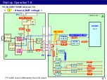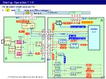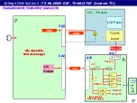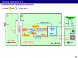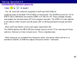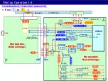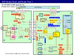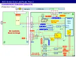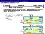
The 12V is also supplied to the T-con board as PNL12V. IC8000 outputs the Panel VCC
On signal and switch on Q5200. Then PNL12V is supplied to the T-con board of the LCD
Module.
52
Start up Operation 2-5
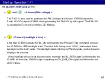
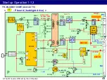
After that, IC8000 outputs the BL_ON command to the P board. That command turns on
VLED output to the backlight on the LCD panel. The backlight starts lighting by PWM
signals, and LCD panel displays the pictures.
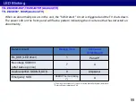
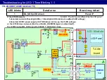
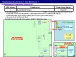
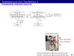
If the backlight drive circuit does not work normally, the BL_SOS signal is informed to the
IC8000. At that time, IC8000 stops outputting the power control signal and blinks the red
LED 1 times.
< and : P board ( backlight drive ) >
6
5
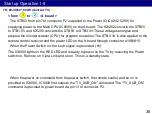
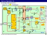
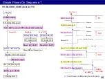
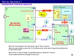
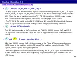
IC8000 outputs the “Power control ” signal. This command separate to TV_PS_ON signal
and TV_SUB_ON signal. TV_PS_ON is connect to the power board via pin 13 of connector
A02. When the power board receives this TV_PS_ON signal from IC8000, mode change
from standby state to working state because of providing high power current.
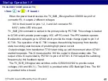
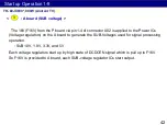
The TV_SUB_ON switch on the Q2101/2102 and 12V go to SUB-Voltage block. Several
power ICs generate the each SUB-Voltages used for signal processing operation.
< : A board (TV_PS_ON, TC_SUB_ON) >
3
< : A board (PNL voltage) >
4
TX- ##JX800-83#*, TH-##JX700* (Android TV)
Содержание TH-40JX700
Страница 2: ...Revision History Version Issued Revised date Revised content Ver 1 0 7th Jun 2021 First version 2 ...
Страница 4: ...1 Lineup and Function Comparison 4 ...
Страница 10: ...2 Function 10 ...
Страница 18: ...3 Board Layout 18 ...
Страница 23: ...23 4 Signal Flow and Troubleshoot of Picture Problem ...
Страница 31: ...31 5 Start up Operation ...
Страница 54: ...54 6 SOS Protection Circuit and Troubleshoot of Power Problem ...

